Well, that was a pretty obvious thread title ") The amp I'm building is the JE Labs/Angela SE 2A3 with the SRPP 6SL7 driver and "my own" PS using a 5AR4. Questions:
The amp I'm building is the JE Labs/Angela SE 2A3 with the SRPP 6SL7 driver and "my own" PS using a 5AR4. Questions:
* What do you think of this layout?
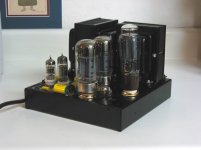
I had no idea the transformers would be that big, or I would have ordered a 17"x14" chassis (that's a 17"x10"). I was thinking about a layout that's symmetrical around a center line with the PS in the middle, but since I can't put the PS transformer, rectifier tube and PS choke in a straight line without making everything almost touch, I think that option is out (I could still leave the rectifier offset from the line of the transformer/choke, but that won't look very nice). With this layout, I'd put the power switch on the left front, and IEC connector and fuse on the left back. Haven't decided how to do the binding posts and RCAs yet, they'll be somewhere on the rear right. Maybe RCAs on the inside and binding posts on the outside. The filament transformers will be under the hood, probably on the left wall or between the PS transformer and choke.
The other layout option would be to move the 6SL7s closer to each other, and then put my hum balance pots on the outsides of the 6SL7s, in front of the 2A3s. That would let me adjust them without having to reach around hot tubes, but would that bring heater currents too close to the 6SL7s?
* Transformer polarity/phase - how important is it to have the 2 filament transformers in phase? Is there any way to tell other than hooking them up and measuring the voltage difference between leads? For the PS choke, does it matter which way I connect it?
* 125ESE wiring diagram - mine didn't come with any, but I'm assuming that I'll be able to find one online somewhere, probably at the Hammond site.
* Transformer grounding - this is important, right? The PS transformer and choke seem to have paint on the outside casing, so I'm not sure if just using bolts and toothed metal washers will make electrical contact. Do I need to scrape the paint off near one of the bolt holes?
* Power up test sequence - does this make sense?
- Power up with no tubes. Make sure secondary voltages are as expected, i.e. the secondaries have been wired correctly.
- Power off, insert all tubes except rectifier, power up. Verify that all filaments light up, filament voltages look good, and HT secondary voltages look good.
- Power off, remove all tubes, insert only rectifier tube, power up. Verify rectifier filaments heat up, and B+ looks correct at output and driver tube plate pin sockets. Voltages will be high because no current is being drawn (this is the step I'm not sure about... is this a good idea?)
- Finally, power up with all tubes inserted.
Thanks a lot in advance, and I'm sure this will be the first post of many.
Saurav
The amp I'm building is the JE Labs/Angela SE 2A3 with the SRPP 6SL7 driver and "my own" PS using a 5AR4. Questions:* What do you think of this layout?
An externally hosted image should be here but it was not working when we last tested it.
An externally hosted image should be here but it was not working when we last tested it.
I had no idea the transformers would be that big, or I would have ordered a 17"x14" chassis (that's a 17"x10"). I was thinking about a layout that's symmetrical around a center line with the PS in the middle, but since I can't put the PS transformer, rectifier tube and PS choke in a straight line without making everything almost touch, I think that option is out (I could still leave the rectifier offset from the line of the transformer/choke, but that won't look very nice). With this layout, I'd put the power switch on the left front, and IEC connector and fuse on the left back. Haven't decided how to do the binding posts and RCAs yet, they'll be somewhere on the rear right. Maybe RCAs on the inside and binding posts on the outside. The filament transformers will be under the hood, probably on the left wall or between the PS transformer and choke.
The other layout option would be to move the 6SL7s closer to each other, and then put my hum balance pots on the outsides of the 6SL7s, in front of the 2A3s. That would let me adjust them without having to reach around hot tubes, but would that bring heater currents too close to the 6SL7s?
* Transformer polarity/phase - how important is it to have the 2 filament transformers in phase? Is there any way to tell other than hooking them up and measuring the voltage difference between leads? For the PS choke, does it matter which way I connect it?
* 125ESE wiring diagram - mine didn't come with any, but I'm assuming that I'll be able to find one online somewhere, probably at the Hammond site.
* Transformer grounding - this is important, right? The PS transformer and choke seem to have paint on the outside casing, so I'm not sure if just using bolts and toothed metal washers will make electrical contact. Do I need to scrape the paint off near one of the bolt holes?
* Power up test sequence - does this make sense?
- Power up with no tubes. Make sure secondary voltages are as expected, i.e. the secondaries have been wired correctly.
- Power off, insert all tubes except rectifier, power up. Verify that all filaments light up, filament voltages look good, and HT secondary voltages look good.
- Power off, remove all tubes, insert only rectifier tube, power up. Verify rectifier filaments heat up, and B+ looks correct at output and driver tube plate pin sockets. Voltages will be high because no current is being drawn (this is the step I'm not sure about... is this a good idea?)
- Finally, power up with all tubes inserted.
Thanks a lot in advance, and I'm sure this will be the first post of many.
Saurav
OK, if I move the transformers right to the edge of the chassis, I can just about fit the rectifier between the PS choke and transformer. That gives me around 3/4" clearance on both sides of the paper box for the rectifier tube, so it'll be a hair more for the actual tube.
Is that better? I could also rotate all transformers and have the 125ESEs along the back edge. That would put them a little closer to the PS trafo, but give a little more room for the 2A3s.
I'm sorry about the flash reflection off the chassis, the protective plastic layers are still on.
And this is the largest aluminum chassis that Angela carries, I double checked that. So I could exchange it for a bigger steel chassis (which would be harder to drill and Morgan Jones recommends against using steel), otherwise returning it will be a little difficult, since the first thing I did was to tear up my invoice and throw it away (it had my credit card number on it).
An externally hosted image should be here but it was not working when we last tested it.
An externally hosted image should be here but it was not working when we last tested it.
Is that better? I could also rotate all transformers and have the 125ESEs along the back edge. That would put them a little closer to the PS trafo, but give a little more room for the 2A3s.
I'm sorry about the flash reflection off the chassis, the protective plastic layers are still on.
And this is the largest aluminum chassis that Angela carries, I double checked that. So I could exchange it for a bigger steel chassis (which would be harder to drill and Morgan Jones recommends against using steel), otherwise returning it will be a little difficult, since the first thing I did was to tear up my invoice and throw it away
(it had my credit card number on it).You should be fine. A trick for determining the best alignment of the power and output iron is to power up the power transformer and hook a volt meter to the input side of the output iron and measure mV AC. Your looking for the lowest number you can achieve by turning them in different configurations. This is help to minimize induced hum.
Here is a heavely modified Dynaco Mark 3, and you thought yours was close.
Here is a heavely modified Dynaco Mark 3, and you thought yours was close.
Attachments
Here is heavely modified Dynaco Mark 3, and you thought yours was close.
Well, yes, but that was probably designed by someone with a little more experience than me
I'll try out the voltmeter solution, though it would make me nervous to have all the secondaries unconnected. I guess I could wire-nut each one individually.
How bout a breadboard
I don't have the experience of a lot of folks here but how bout a breadboard instead of committing it to final form. It is a nice way to experiment with placement, wire length ectc...and how it effects things. I've been messing around with this stuff for a year and while I got it off the drawing board I have not gotten off the breadboard to date. It makes those almost inevitable mistakes easier to handle, allows you to focus on sonics, and makes tweaks and changes less traumatic too. At least, I think, for a beginner.
Cheers
Craig Ryder
saurav,
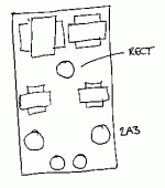
try this
+--------------------------------+
|................................|
|..OOO........PPPPP.........OOO..|
|..OOO........PPPPP.........OOO..|
|................................|
|...6.........CCCCC..........6...|
|...2.. ........R............2...|
|................................|
+--------------------------------+
where OOO is the OPT, PPP is the power trafo, CCC is choke, 6 is 6SL7, 2 is the 2A3 and R is the rectifier.
it seems to me you have enough room
here's the wiring diagram of the 125ESE - http://users.starpower.net/je2a3/125SE-1.jpg
* Transformer grounding - *
I didn't do that
* Power up test sequence - does this make sense?
- Power up with no tubes. *
right
- Power off, insert all tubes except rectifier, power up. *
right
- Power off, remove all tubes, insert only rectifier tube, power up. *
Yes, your B+ will be off
- Finally, power up with all tubes inserted.
I'd like to add that you do some resistance checks just to make sure you don't have a cold solder.
Good luck, it will be fun.
where OOO is the OPT, PPP is the power trafo, CCC is choke, 6 is 6SL7, 2 is the 2A3 and R is the rectifier.
Would you mind explaining why you suggest this layout? I had R between PPP and CCC because that's how the wiring will flow. Also, why do you recommend placing the 6SL7 closer to OOO than the 2A3?
I'd like to add that you do some resistance checks just to make sure you don't have a cold solder.
Of course, that's before I power it up for the first time.
So it looks like many people don't bother with grounding the transformer frame?
Ryder,
I was thinking about breadboarding, but I don't have a dedicated space to work in, so that will be difficult to pull off. I'm toying with the idea of a "semi-breadboard" kind of a thing, where I fix the locations of the components, but hook them up using clip leads first to make sure everything's correct, and solder the connections later. That will make it easier to leave everything in a corner of the living room when I'm not working on the amp.
I liked the layout of your second set of photos better, but how about doing it like this? The (hot) 2A3's are now at the edge of the chassis and can cool better, you have shorter wiring in the PSU, the input valves are close together (makes input wiring and earth busbars easier) and a long way away from the PSU, it's symmetrical (almost) and all the glowing glass is at the front where it belongs. The slight downside is that the rectifier is still in the middle of the chassis, but it won't get as hot as the output valves. If you were confident of your metalwork, and worried about its temperature, you could drill ventilation holes around it. I probably wouldn't bother.
My drawing suggests that the mains transformer's coil points at the input valves. Of course it doesn't. Its coil should point horizontally.
My drawing suggests that the mains transformer's coil points at the input valves. Of course it doesn't. Its coil should point horizontally.
Attachments
You know, that's almost exactly how the amp is laid out on the Angela website. My only hesitation with that layout is that the RCA connectors and binding posts would need to be on the sides of the enclosure, and the power switch would need to be in the back. I think I can live with that though - the 2A3s are taller than I expected, and this amp won't fit in my audio rack, so it'll have to go on the top shelf. That will help with cooling, and it'll also be easier to reach around to the back of the amp.
That's the thing I'm least confident about, followed by my spray painting skills. Would you recommend ventilation holes around the 2A3 tubes? I think I could manage that if I didn't put the holes too close to the socket hole.
Could you explain that please? I'm assuming that the large rectangle in the middle indicates the laminations, and the two smaller rectangles on the sides indicate the bell endcaps?
If you were confident of your metalwork
That's the thing I'm least confident about, followed by my spray painting skills. Would you recommend ventilation holes around the 2A3 tubes? I think I could manage that if I didn't put the holes too close to the socket hole.
My drawing suggests that the mains transformer's coil points at the input valves. Of course it doesn't. Its coil should point horizontally.
Could you explain that please? I'm assuming that the large rectangle in the middle indicates the laminations, and the two smaller rectangles on the sides indicate the bell endcaps?
OK, I was looking through the Bottlehead boards about transformers and metal top plates because I remember seeing some discussions on this in the past. It seems like a lot of people there mount the transformers on rubber/vinyl grommets to mechanically and electrically isolate it from the chassis, and run a drain wire from the frame to earth/safety ground. That seems to make sense to me, and a ground lug placed under the transformer's foot with the paint scraped off the underside would be an easy way to implement that ground connection. That will also allow me to paint the chassis without worrying about masking off the transformer mounting holes to maintain electrical contact.
Thanks for that tip.
Thanks for that tip.
Saurav said:You know, that's almost exactly how the amp is laid out on the Angela website.
I didn't look, honest.
My only hesitation with that layout is that the RCA connectors and binding posts would need to be on the sides of the enclosure, and the power switch would need to be in the back.
What's wrong with having the RCAs at the front, between the input valves, or are you going to put a volume control and selector switch there? The binding posts could go at the sides, or the back (twist the leads to them). The back is the best place for the mains switch, makes you think harder about turning it off...
I wouldn't bother with ventilation holes. With the 2A3s at the edges, they will cool nicely, and drilling ventilation holes exposes less-than-perfect metalwork.
Your assumption is right. For your mains transformer and choke, the coil is oriented along the direction of the laminations. The mains transformer should not point its coil at the input valves, but the choke produces a rather smaller leakage field, so it can.
I didn't look, honest.
I didn't think you did
What I was trying to say was, if two people independently arrived at the same (or similar) layout, there's probably a reason behind it.What's wrong with having the RCAs at the front, between the input valves
Just the cable routing for the interconnects. Of course, I could rebuild my linestage and put one set of outputs in the front, and run cables up the front of the rack. Right now, all cables are in the back, so putting the RCAs in front would mean running cables beside, or over, the tubes. Most of my interconnects are DIY with fairly stiff coax, so this may not work very well, as it'll be hard to lay the cables down beside the chassis.
and drilling ventilation holes exposes less-than-perfect metalwork
Good point that I hadn't thought about.
- Status
- This old topic is closed. If you want to reopen this topic, contact a moderator using the "Report Post" button.
- Home
- Amplifiers
- Tubes / Valves
- Starting on my first amp, have some questions