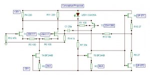
Output board from an all-FET preamp. Top section of the pic shows the L-channel, which is working fine. Bottom shows the R-channel, which originally was not working at all, but after sitting in the back of the shop for six months and putting it back on the bench is suddenly passing a signal. I do not expect it to continue to do so.
I've marked the measured voltages & currents, and you can see that the R channel has a real offset problem at the output, and is the most likely symptom of the falling device (and there's a lot more current flowing through the output stage of the problem channel). It seems to me that the suspicious device might be Q206, but before I start searching for replacement devices I wanted to get some feedback from of the more FET experianced guys...
Any input is appreciated. Thanks guys!
I've marked the measured voltages & currents, and you can see that the R channel has a real offset problem at the output, and is the most likely symptom of the falling device (and there's a lot more current flowing through the output stage of the problem channel). It seems to me that the suspicious device might be Q206, but before I start searching for replacement devices I wanted to get some feedback from of the more FET experianced guys...
An externally hosted image should be here but it was not working when we last tested it.
Any input is appreciated. Thanks guys!
hi echowars,
these type of problems can be tricky, especialy the intermitant nature of the problem, problem is that just about all the devices in the circuit are DC coupled and any one of them maight be suspect how i would tackle the job is
first to make sure that their is no problem with the power supply check with a scope, compare channels.
quick in circuit check, all R's, again compare readings with other channel 5mins (has been known)
then wile monitoring the output with a scope DC coupled or high impedance DC voltmeter, what you a looking for is drift and eratic readings.
then cooling the transistors with a sqib of freezer spray locally will very often show up a bad device, this in incombination with the wifes hair dryer to heat up and cool down the suspect device. if you do the same to the good channel to make comparisons along the way the bad transistor will most of the time reveal itself as extra sensitive to heat or cold or both.
if the above fails then you are down to swapping devices from one channel to the other.
good luck
Source voltages from the supply are stable and clean. Resistors all measure within 2% of tolerance. I've tried freeze-spray, and the devices seem to be unaffected by it. I had hoped that the schematic with voltages and currents labled might give some insights...
While the ability to pass a signal seems to be intermittent, the ugly offset at the output of this board is constant. I hate to swap parts from side to side, but I'll do that if nothing is obvious to any of the members here on the forum.
While the ability to pass a signal seems to be intermittent, the ugly offset at the output of this board is constant. I hate to swap parts from side to side, but I'll do that if nothing is obvious to any of the members here on the forum.
the currents seem to vary a lot.
Check the LTP currents again. eg R203 has 31-30.6=0.4V across it. 240r will pass ~1.7mA, not 1.1mA
Note, the input difference = output offset / 10.
That confirms that the 10k and 1k1 are the NFB resistors.
The 0.32volts on the -IN of the intermittent possibly indicates that one of the input pair is damaged.
Before replacing any semiconductors see if you can trim some of the FET CCS resistors to get better balance of currents across the LTP pairs.
The supply voltages as given (+/-31V) are approximate. The -31V supply on the lower board actually measures about -30.89V or so.AndrewT said:the currents seem to vary a lot.
Check the LTP currents again. eg R203 has 31-30.6=0.4V across it. 240r will pass ~1.7mA, not 1.1mA
Yes, they are. R010 connects to the junction of R207 & R208.Note, the input difference = output offset / 10.
That confirms that the 10k and 1k1 are the NFB resistors.
Or simply 1/10th of the DC voltage being fed back to the - input.The 0.32volts on the -IN of the intermittent possibly indicates that one of the input pair is damaged.
Suggesting R202 trimming?Before replacing any semiconductors see if you can trim some of the FET CCS resistors to get better balance of currents across the LTP pairs.
See above.boholm said:On the resistor R010 (10K) - what is the DC voltage on the right side?
And where does it go?
The solder joints look great...the level of workmanship on this thing is first-rate. And there are no electrolytic caps to leak on the boards...all are film caps of one type or another.
Well, the offset at the output is actually 10x that, or -3.2V. But I'd not lose a lot of sleep over a few hundred millivolts of offset (3.2V is a different story), as the output is cap-coupled. But yeah, a better balance would be nice.
Anyway, I took Andrew's advice and removed the differential transistors. One of them is toast.
I took the two diff-pair transistors out of the other channel to confirm, and once installed the offset went from -3.2V to 0.77V. Indicates that the input is not well-balanced, but I can worry about that later.
The schematic says that these are 2SK177-Y, but the actual part used is the UN07. Both seem to be very hard to get, but I'd probably have better luck finding the 2SK117-Y. Any suggestions on where to look? Or of a good substitute? I'd need to get a 15 ~ 20 of them to match a pair, I'd imagine. Or maybe someone sells a matched pair?
2SK170GR
Vgds = 40V
VgsOff = -0.2 ~ -1.5
Idss = 2.6mA ~ 6.5mA
2SK117Y
Vgds = 50V
VgsOff = -0.2 ~ -1.5
Idss = 1.2mA ~ 3.0mA
The GR version of the K117Y has a Idss of 2.6 to 6.5mA, and there's a auction for a bunch of 2SK117GR's where I can possibly match a few of the GR devices at the low end of the range. That might be easier than tracking down the 2SK170 devices.
Reduce the value of of R203 (240 Ohm)
until you get close to 0 Volt at output.
You could use a temporary trimpot of 500 Ohm (or maybe 250/220 Ohm) to find out a good value for R203.
Altenatively you can try with: 220, 180, 150 Ohm etc. resistor for R203
What this does is, it increases current in Q202
and so the voltage at gate will go from -0.32 Volt ->> 0.0 Volt
At the same time, of course DC-offset at output will go from -3.2V ->>> 0.0 Volt
Because when higher current -Vgs will decrease = Gate becomes more positive
I am almost sure, there is nothing wrong with any JFET.
It is only a question of set the currents right.
----
About the small difference of current in output stages:
8 mA vs. 11 mA is no big deal.
If you like you can try increase source resistors R207, R208 from 27 Ohm to 33 Ohm
to bring down 11 mA to get closer to 8 mA.
But shouldnt be necessary.
/lineup
The schematic says that these are 2SK177-Y, but the actual part used is the UN07. Both seem to be very hard to get, but I'd probably have better luck finding the 2SK117-Y. Any suggestions on where to look? Or of a good substitute? I'd need to get a 15 ~ 20 of them to match a pair, I'd imagine. Or maybe someone sells a matched pair? [/B]
Hi EchoWars,
I believe that one matched pair of 2SK170 will be fine. Maybe, all of small signal N-fet with low Vp and high Gm ( eg.: BF862 ) will do because the feedback network.
You will find your fets here
http://www.ampslab.com/components_fets.htm
regards
eD
Thanks for your help. I have a source that can sell me 50 pieces of the 2SK117Y for about $26. Are these parts trustworthy? In other words, are there counterfeit small-signal FET's out there like with many other Japanese transistors? Toshiba seems to show this as a current production part, so perhaps counterfeiting is not as issue, but I've been burnt before...
Roar, if the buy I mentioned above doesn't work out, might you be willing to part with a few devices (at least a couple of matched pairs)?
Roar, if the buy I mentioned above doesn't work out, might you be willing to part with a few devices (at least a couple of matched pairs)?
EchoWars said:Thanks for your help. I have a source that can sell me 50 pieces of the 2SK117Y for about $26. Are these parts trustworthy? In other words, are there counterfeit small-signal FET's out there like with many other Japanese transistors? Toshiba seems to show this as a current production part, so perhaps counterfeiting is not as issue, but I've been burnt before...
Roar, if the buy I mentioned above doesn't work out, might you be willing to part with a few devices (at least a couple of matched pairs)?
I don´t know if there are fakes small devices like k117 but if your problem is on the diff input, it may work with a lot of devices. The feedback take care of it.
regards
eD
- Status
- This old topic is closed. If you want to reopen this topic, contact a moderator using the "Report Post" button.
- Home
- Amplifiers
- Solid State
- FET Line-Stage with Issues