Having recently been considering class AB input stages, I wondered how it might be possible to reduce the added complexity of multiple current sources that the long tail pair type often use. One possibility is to use the LTPs' own current mirrors as current sources.
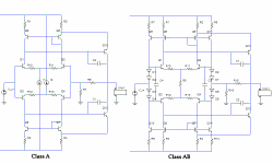
Now, class AB LTP input stages are symmetrical, so you can't just put current sources in them because the VAS quiescent current becomes undefined. So the first thing to do is apply some current feedback from the VAS. This yields the circuit on the left in the attached picture.
Changing this to class AB yields the circuit on the left. The LTPs are connected at the tails and their tail current sources removed so that each LTP provides the current for the other, and the bases are biased on with diodes. The current can increase past the quiescent current, hence the class B part. The constant currents that feed the diodes are simply provided by adding extra outputs from the current mirrors (Q9/11/13/14). Note that the emitter resistors for these extra current source transistors can be larger than those in the main current mirror to reduce the current through the diodes, for efficiency (Widlar current mirror). It would also be possible to use a "diamond buffer" arrangement to provide the bias voltage instead of diodes, giving higher input impedance.
The whole point of class AB input stages is to increase slew rate, so I simulated that and got 60V/us, compared to 30V/us for the class A version. This is with relatively large 100pF Miller compensation capacitors, LTP tail current at 4.7mA (I1 and I2 in the class A circuit, the current through R5 in the class AB circuit) and VAS current also at a conservative 4.7mA. GBP, phase margin and distortion are all approximately the same for both circuits, so the main compromise is between slew rate and complexity.
Higher slew rates would be possible by increasing LTP current and decreasing the value of R5 and/or the emitter degeneration resistors (which are inextricably linked to the quiescent current, unless the bias scheme is changed). Insanely high slew rates are possible.
So what do you do with all this slew rate? I dunno, but it's interesting anyway.
Note that the capacitors C3/4 were needed to prevent overshoot in the sims, but might not be needed in a real circuit.
EDIT: The image was too big, so I chopped the supply voltages off.
Attachments
Good work!
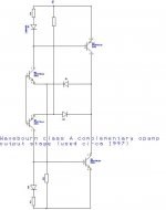
Here is what I used when wanted as simple as possible complementary class A opamp with gain = 1.
A first, I replaced transistors in current mirrors by diodes.
Second, I replaced transistors in LTP pairs by diodes. And third, I used resistors in tails so currents depend on voltage. LTP currents were adjusted by resistors in tails to get no more than max needed current swing on the real output load, so in case of accidentally lower load resistance it protected itself limiting the current. Surprisingly, the sound was vacuum tube-like!
Attachments
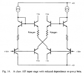
andy_c said:Just curious - have you seen the class AB input stage from the Smith, Koen and Witulski paper? I think that paper is on OS's site. Here's a pic.
On top of my head, before any analysis (manual or Spice) this schematic looks very depending on matching and resistor ratios. If I am correct, then there's little chance to make it working with discretes (assuming it would make any sense to use it). Such schematics were extremely interesting about 30 years ago, when the lateral pnp in standard linear processes was a PITA for any analog designer.
I designed a high-performance opamp for driving low-Z headphones (50R and under) a while back and have been refining it for a while. The idea was from the Smith et al paper referenced earlier (Figure 13, specifically). You might be interested in it. Performance is absolutely excellent (I have an AP 2722 to play with intermittently so I can get some real numbers).
It is fully class-AB, including the input stage, which is a dual diamond buffer arranged as a fully-differential V-to-I converter. A simple current-mirror gain stage slews a gang of output MOSFETs. All devices are TO-92; my stereo prototype is on a 4.5x4.5" protoboard along with a DC servo. The gate-drain capacitance of the FETs is enough to provide good compensation. It's picky about decoupling around the input stage, so the schematic is a pseudo-layout to show what is needed.
Basic specs:
* Unity gain bandwidth: 35MHz (measured; unity gain stable; 60 deg phase margin)
* Open-loop bandwidth: ~4KHz (approx. 80db OLG)
* Slew rate: 1000v/uS (!!!) (measured; 10v step on 24v rails)
* THD/IMD: under -110dB (<20khz sine at around 2v into 50R), 2nd harmonic
* Idle current: about 12mA for input and gain stages, output set at 20mA
Attachments
syn08 said:On top of my head, before any analysis (manual or Spice) this schematic looks very depending on matching and resistor ratios.
I think you'd want all four resistors equal in this thing, and all NPNs and PNPs to be the same type. If you go around any loop from -Vin to +Vin, there's two resistors (same as a normal diff amp) and four Vbe's. So I'd expect it to be somewhat worse than a normal diff amp for offset behavior. I wouldn't dismiss it as unusable in a discrete design without some more careful investigation though.
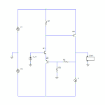
I haven't seen that before. It looks like it might be a solution to a problem I was contemplating some time ago for using the attached input stage topology in an audio amp. It's functionally identical to an class AB LTP but uses a complementary pair and both outputs are non-inverting. I've used it for things like voltage regulators and other places where the 2*Vbe offset between the inputs doesn't matter or is even useful. Like the one you posted, it's interesting because you get the output from both ends, opening up novel VAS possibilities.andy_c said:Just curious - have you seen the class AB input stage from the Smith, Koen and Witulski paper? I think that paper is on OS's site. Here's a pic.
That's one of the problems with these things - as they get faster, they become very good not only at amplifying audio, but also anything else that comes near, like mobile phones, switching power supplies, and alien mind control rays.sparcnut said:...It's picky about decoupling around the input stage, so the schematic is a pseudo-layout to show what is needed...
Attachments
andy_c said:
I think you'd want all four resistors equal in this thing, and all NPNs and PNPs to be the same type. If you go around any loop from -Vin to +Vin, there's two resistors (same as a normal diff amp) and four Vbe's. So I'd expect it to be somewhat worse than a normal diff amp for offset behavior. I wouldn't dismiss it as unusable in a discrete design without some more careful investigation though.
Offset is only one side of the story. I would be more concerned about poor CMRR (in a discrete implementation).
What would be the use of this configuration in the discrete world? We already have all the PNP's we need, beta, Ft, you name it.
syn08 said:What would be the use of this configuration in the discrete world?
Well, the thread is about class AB input stages, and that's what it is. So it would be for high slew-rate applications.
andy_c said:
Well, the thread is about class AB input stages, and that's what it is. So it would be for high slew-rate applications.
Ah, ok

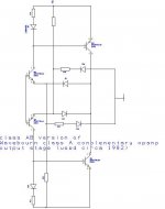
Here is class AB version used later to replace a tube output stage in guitar amp with dead output transformer.
Again, resistors were used to bias in both class A and class B modes (actually, output transistors were not leaving class A region, rather current was limited)
Again, resistors were used to bias in both class A and class B modes (actually, output transistors were not leaving class A region, rather current was limited)
Attachments
A little googling and I find a CMOS version of this same topologyandy_c said:Just curious - have you seen the class AB input stage from the Smith, Koen and Witulski paper? I think that paper is on OS's site. Here's a pic.
Maybe you'll find some inspiration here:
http://www.diyaudio.com/forums/attachment.php?s=&postid=1443043&stamp=1204368106
http://www.diyaudio.com/forums/attachment.php?s=&postid=1443043&stamp=1204368106
darkfenriz said:Maybe you'll find some inspiration here:
http://www.diyaudio.com/forums/attachment.php?s=&postid=1443043&stamp=1204368106
Pretty VSOPish
Maybe you'll find some inspiration here:
http://www.diyaudio.com/forums/atta...tamp=1204368106
too many freeekin' diodes..
 maybe a couple white LED's
 OS
Wavebourn,
How was it verified? Those diodes do surely more damage than class AB switching does. It`s considerably more appealing than Steve Dunlap`s arrangement, anyway.(actually, output transistors were not leaving class A region, rather current was limited)
Lumba Ogir said:Wavebourn,
How was it verified? Those diodes do surely more damage than class AB switching does. It`s considerably more appealing than Steve Dunlap`s arrangement, anyway.
The owner (guitarist) was happy. He got his amp fixed so he could play, Also, they connected it to the bass guitar cab (as I suggested to try) and were surprised: they knew that guitar amps sounded weak with bass guitars, but as the result of a "fast fix" it was "a miracle". As I know he later decided to leave that "fast fix" as is, instead of returning back to output tubes with an output transformer.
Mind you, no voltage gain here, but AB is exceedingly smooth.
(VAS?) figures to be two silicon emitter drops, minus the two
Shottkys and some series resistance.... Is that correct?
I still havn't figured why Schottkys seem essential to make AB
cross without a glitch? If I lower VAS by other means, doesn't
have the same effect...
(VAS?) figures to be two silicon emitter drops, minus the two
Shottkys and some series resistance.... Is that correct?
I still havn't figured why Schottkys seem essential to make AB
cross without a glitch? If I lower VAS by other means, doesn't
have the same effect...
Attachments
- Status
- This old topic is closed. If you want to reopen this topic, contact a moderator using the "Report Post" button.
- Home
- Amplifiers
- Solid State
- Self-biasing class AB input stage