Hi all. ")
I have a 3 sources with optical digital outputs that I want to use with a reasonable DAC. The sources are a sky TV digibox, Pioneer DVD payer and Sony PS2. They aren't priority sources but If I can find a DIY DAC at a good price I expect it might provide slightly better sound quality into my Amp.
Is there a good DAC with optical switchable inputs available in kit form?
Any advive would be greatly appreciated.
Rgds
Mike.
You could use this in front of any diy dac:
http://www.twistedpearaudio.com/digital/cs8416mux.aspx
Although, you would have to convert the Optical signals to Spdif first, which is not much of a problem, I believe.
http://www.twistedpearaudio.com/digital/cs8416mux.aspx
Although, you would have to convert the Optical signals to Spdif first, which is not much of a problem, I believe.
Cheers.
Bit pricey for what I intend to use it for though.
I would even consider a secondhand one but I need at least 3 optical inputs, unless its an easy mod to convert from coax to optical and vice versa?
There's a couple of cheap DIY ones on eBay:
http://cgi.ebay.co.uk/ws/eBayISAPI.dll?ViewItem&rd=1&item=140293735645&ssPageName=STRK:MEWA:IT&ih=004
http://cgi.ebay.co.uk/ws/eBayISAPI.dll?ViewItem&rd=1&item=290287927373&ssPageName=STRK:MEWA:IT&ih=019
Maybe you can multiply the optical input of one of these DACs by DIYing yourself a switch with multiple optical in and one optical out.
I'm thinking about building a switch for my low priority devices (DVDplayer, HDDrecorder, digital TV decoder) to use them on the optical input of my DAC. That way the electrical inputs remain free for HQ audio equipment.
I have some ideas of how to build one. I think of combining several optical and electrical inputs with one optical output. But right now it's no more than ideas...
It may be a long shot, but is this something that would work? It's not "industrial grade", from the looks of it, and it's not priced as such, either:
Nyrius SW100 Digital Audio Optical Toslink 3-Way Selector Switch for Fiber Optic Home Theater Connections
http://www.amazon.com/Nyrius-SW100-Digital-Selector-Connections/dp/B000812QC6
It also looks like "Cables-To-Go" has something similar:
Cables-To-Go "Digital Explorer" Optical Switch
I would have thought that you would have to implement something like this by using three separate S/PDIF-Toslink receivers which convert the optical signal to electrical, then use a MOSFET-type switch to connect the desired input to the output(s). I guess you could do this a whole bunch of different ways, though....
HTH
mikesnowdon said:That sounds like the kind of thing I need too.
I have no idea how to switch optical though, isn't it done with fiber optics?
Mike.
The optical switches that Cliff45 linked to indeed seem to work with optics as I dont think there's any AC adapter. If you're going fully optical, this might be a simple yet effective way to do it. But keep total fibre cable length short, especially when using plastic fiber cable (almost all of the cheaper ones). Glass fibre cable is better.
Cliff45 said:It may be a long shot, but is this something that would work? It's not "industrial grade", from the looks of it, and it's not priced as such, either:
Nyrius SW100 Digital Audio Optical Toslink 3-Way Selector Switch for Fiber Optic Home Theater Connections
http://www.amazon.com/Nyrius-SW100-Digital-Selector-Connections/dp/B000812QC6
It also looks like "Cables-To-Go" has something similar:
Cables-To-Go "Digital Explorer" Optical Switch
These look fine for use in non critical sources, just as Mike intends.
I would have thought that you would have to implement something like this by using three separate S/PDIF-Toslink receivers which convert the optical signal to electrical, then use a MOSFET-type switch to connect the desired input to the output(s). I guess you could do this a whole bunch of different ways, though....
That's the idea I have because I want a switch with multiple inputs of both optical and coaxial. But someone already DIYed just that, look here.
Mike, if you can read schematics, you can recognise the circuits needed for optical -> coax and vice versa.
I'm going yo build this, but without the use of a microprocessor. That looses some functionality (display) but I won't need a programmer or processor.
The multiplexer (74HCT251) has eight selectable inputs that can be selected by a combination of low and high signals on s0, s1 and s2. I can make it a lot easier by limiting the inputs to 4 by connecting s2 to GND permanently. To be continued...
This looks ideal.
Like you suggest a simpler version should be doable for me. The switches on Amazon look ok but I'd rather have something all-in-on box with a simple rotary switch on the front. If you go ahead with this please keep me posted, it will be easier for me if I can follow someone building a similar thing.
Like you suggest a simpler version should be doable for me. The switches on Amazon look ok but I'd rather have something all-in-on box with a simple rotary switch on the front. If you go ahead with this please keep me posted, it will be easier for me if I can follow someone building a similar thing.
Today I breadboarded part of the circuit to test if my approach to switching between channels will work. Answer: it will.
In the attachment you can see how I was originally planning to switch between channels. Using some pull up resistors combined with pull down transistors driven by a 2 pole 4 position rotary switch to select between channels.
Explanation about the switch: 2 pole switch with 4 positions (just like in a switch box to connect 4 stereo sources to one input on a stereo amp). Both poles per position are "coded" as in the truth table next to the schematics (note that the transistor inverts the logical signal: H base means L collector as the emitter is connected to GND).
Attachments
But then I thought: this can be much simpler using the same switch but ditching the transistors and resistors.
Unless someone can come up with a reason why the first idea would be better, I'm going for this one instead.
Without the transistors, the "coding" of the switch does not need to be reversed.
Edit: I just noticed I forgot to connect pin 7 to ground in the schematics. Without it, there'll be no output.
Attachments
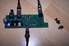
Been busy building the S/PDIF-switch on a Veroboard. I found an offcut that looked big enough and thought why not?
It's not finished yet, but the two optical inputs and optical output are functional. In the picture music was playing through the switch!
It's not finished yet, but the two optical inputs and optical output are functional. In the picture music was playing through the switch!
Attachments
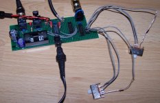
Today I finished the wiring for the coax inputs and replaced the jumpers on S0 and S1 with some change over switches (SPDT).
To prevent damage in the (unlikely) event of a short in the switch between GND and Vcc I added 10 k resistors in the Vcc line to the switch, as you can see in the attachment.
Tomorrow I'll get a 74HCT04 for the S/PDIF output and finish that too (the middle IC in the picture is not a HCT, it's just taking up space so that I wouldn't wire across there).
Attachments
mikesnowdon said:Cheers.
Bit pricey for what I intend to use it for though.
I would even consider a secondhand one but I need at least 3 optical inputs, unless its an easy mod to convert from coax to optical and vice versa?
There's a couple of cheap DIY ones on eBay:
http://cgi.ebay.co.uk/ws/eBayISAPI.dll?ViewItem&rd=1&item=140293735645&ssPageName=STRK:MEWA:IT&ih=004
http://cgi.ebay.co.uk/ws/eBayISAPI.dll?ViewItem&rd=1&item=290287927373&ssPageName=STRK:MEWA:IT&ih=019
Any idea on he quality of these DAC's? Can they be modded for better sound perhaps?
mikesnowdon said:Wow Jitter, amazing work!
When all this is finnished will you provide a BOM and schematics for breadboard to a newbie? I'll need a hand to build this
Thanx!
The schematics are more or less as per the design I already provided a link to. All the different blocks in there are drawn separately, it's just a matter of connecting the traces with the same names.
The major difference is the in way channels are being switched. The original design uses a processor for that with infrared input and a display to tell which channel is selected. All this will be replaced by a two-pole four-position rotary switch.
The switching is achieved as follows (take a look at the attachment):
You need to "tell" the multiplexer which of the eight channels to choose from to relay to the output. In the original design this is already limited to the first four by connecting C to GND permanently, and that's what I've done too. That leaves inputs D0...D3 available. Note that I previously used S0, S1 (as per the Philips datasheet of the 74HCT251) which corresponds to A and B in these and the original schematics.
Selection is made by a binary code on A and B, Y is the output:
A - B -> Y
0 - 0 -> D0
1 - 0 -> D1
0 - 1 -> D2
1 - 1 -> D3
0 is achieved by wiring to GND, 1 to Vcc
The output of the 2 pole rotary switch is connected to A and B of the multiplexer. Each of the four inputs must be coded to get the same result as in the truth table above.
Position 0 (for D0): pole A to GND, pole B to GND
Position 1 (for D1): pole A to Vcc, pole B to GND
Position 2 (for D2): pole A to GND, Pole B to Vcc
Position 3 (for D3): pole A to Vcc, pole B to Vcc.
(I chose the same names for the poles and switch-postions based on the names of the pins of the multiplexer to prevent mistakes.)
Have you allready got a DAC for this?
Yes, I have a Micromega DAC1. It has three inputs: one Toslink, one coaxial and one AES/EBU. I'm using the coax input for my Shigaclone project (which I may fit with an AES/EBU output later on). I want to use the optical input for my less critical (sound quality-wise) devices, all of wich have mediocre analogue outputs. They are a DVD-player, a HDD-recorder and a digital TV-decoder. Like you I thought these would benefit from connecting to external DAC and it seemed nicer to use all of them on the optical input instead of just one.
mikesnowdon said:
Any idea on he quality of these DAC's? Can they be modded for better sound perhaps?
I don't know these, but considering the price they must have cut costs in several places. So yes, if the basics of the design are sound, improvements by modding seem very possible to me.
Edit: in the attachment A0 means pole A of position 0, B0 pole B of position 0, and so on.
Attachments
Cool
So is this the finished article then or just a prototype? Will you be taking it any further perhaps designing a PCB?
I wish I could contribute to this project but my knowledge is very limited, I'm not sure I even know what a multiplexer is or what it does? Also how does the optic signal become electrical? I assume its converted so and then back to optical again at the output?
I can read a schematic and solder so I should be able to build this if there is a parts list?
Whats the PSU requirement?
I suppose there is a good chance they might sound better than the output stages in the DVD, Digibox, and PS2. And the key components are through hole so upgrades are easy, things like DC blocking caps, PSU smoothers etc.
Thanks,
Mike.
So is this the finished article then or just a prototype? Will you be taking it any further perhaps designing a PCB?
I wish I could contribute to this project but my knowledge is very limited, I'm not sure I even know what a multiplexer is or what it does? Also how does the optic signal become electrical? I assume its converted so and then back to optical again at the output?
I can read a schematic and solder so I should be able to build this if there is a parts list?
Whats the PSU requirement?
I don't know these, but considering the price they must have cut costs in several places. So yes, if the basics of the design are sound, improvements by modding seem very possible to me.
I suppose there is a good chance they might sound better than the output stages in the DVD, Digibox, and PS2. And the key components are through hole so upgrades are easy, things like DC blocking caps, PSU smoothers etc.
Thanks,
Mike.
mikesnowdon said:Cool
So is this the finished article then or just a prototype?
Will you be taking it any further perhaps designing a PCB?
It's the (nearly) finished article. I intend to build just this one, that's why I didn't bother designing a pcb and go through the process of etching and drilling it. But the original designer already produced a pcb layout. This would still be usable with the switch. It's just be a matter of not placing the microprocessor/IR-receiver/display and wiring the rotary switch to A and B of the 74HCT251.
I used another type of optical receiver than in the original design. It won't fit on that pcb-design (I used TORX173, the TORX177 in the original design has a different shape).
I wish I could contribute to this project but my knowledge is very limited, I'm not sure I even know what a multiplexer is or what it does?
A multiplexer makes clever use of an underutilised bandwidth of a line by squeezing more than just one signal onto it.
Imagine a datablock being sent by a source at regular intervals with nothing in between. This empty space could easily be used to send other datablocks from other sources over the same line. At the other end of the line a demultiplexer sorts these datablocks and sends them to the several different recipients. This of course happens at very high speeds and is repeated continually.
The benefit is that you need far less wiring to transmit the same amount of data than without multiplexing and demultiplexing.
With the S/PDIF switch we're using the multiplexer merely as a switch to select between sources.
Also how does the optic signal become electrical? I assume its converted so and then back to optical again at the output?
That's correct. The black boxes that connect to the optical cable do exactly that. The ones at the input are receivers, the one at the output is a transmitter.
I can read a schematic and solder so I should be able to build this if there is a parts list?
Yes, that's enough to make this thing. It's a matter of making the right connections. The hard part of dreaming all this up has already been done for us. I just made some minor modifications (that does require some knowledge) to adapt the design to my needs.
The parts list can be constructed by looking at the schematic because everything is in there. But I will make a BOM of my creation when I'm finished.
Whats the PSU requirement?
You need a stabilized 5 V DC power supply. I used a 7805 volltage regulator (on the heatsink in the picture) fed by a 12 V adapter. Without the coaxial output installed yet it draws >110 mA from the adapter.
I suppose there is a good chance they might sound better than the output stages in the DVD, Digibox, and PS2.
Quite possible. These devices usually have very few but highly integrated ICs doing everyhting. It's a miracle that they sound decent at all...
Cheers.
As long as its an improvement on what it replacing then for the money is a good bet! I prefer the look of this one as it has some decent components like BB OPA2134 output, DAC chip and Nichicon/Oscon caps. There appears to be an on board PSU which I could tap into for the input selector.
These devices usually have very few but highly integrated ICs doing everyhting. It's a miracle that they sound decent at all...
As long as its an improvement on what it replacing then for the money is a good bet! I prefer the look of this one as it has some decent components like BB OPA2134 output, DAC chip and Nichicon/Oscon caps. There appears to be an on board PSU which I could tap into for the input selector.
- Status
- This old topic is closed. If you want to reopen this topic, contact a moderator using the "Report Post" button.
- Home
- Source & Line
- Digital Line Level
- DIY DAC with input switchingon a budget?