Hi all,
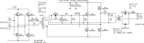
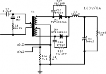
I have a success with my 160V/8A but in full bridge topology (no more flyback above 200W!). But it still blows with 7A load. I see nice waveforms on gates with slope below 350nS, no rings on primary and fully stable work without noise or heat with 6A load.
Any comment will be grateful.
I have a success with my 160V/8A but in full bridge topology (no more flyback above 200W!). But it still blows with 7A load. I see nice waveforms on gates with slope below 350nS, no rings on primary and fully stable work without noise or heat with 6A load.
Any comment will be grateful.
Attachments

Which part of the circuit blows up?
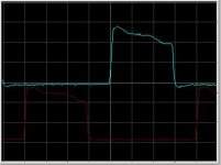
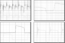
What does the waveforms on T1 secondary look like? I suspect you might need snubbers over the diodes to lessen the spike generated after diodes turn off because of reverse recovery in combination with leakage inductance.
Are you sure L1 is not saturating?
It could also be cross conduction. Which types of FETs do you use? Is it IRFP460, IRFP460N or something else? Regular IRFP460 have pretty high reverse transfer capacitance and will need very stiff turn off and soft turn on drive or negative gate bias when off if you don't want cross conduction.
Hi fob,
Your circuit seems ok, but you could try the following:
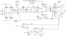
1. For quicker MOSFET gate discharge, add an anti-parallel signal diode across R2 (maybe a 1N4148).
2. At the 270-300v input, you should add an inductor of about 1mH before the 470uF capacitors to limit peak inrush current.
3. Increase the output inductor L1, from 150uH to about 400-500uH.
4. Since your switching frequency is 98kHz, the internal freewheel diode of the MOSFETs may be too slow and thus, cannot protect the MOSFETs from transients, while switching off. That's why, you can add anti-parallel ultrafast recovery diodes across each MOSFET of the bridge.
5. Since your switching frequency is high (98 kHz), you can remove R6 and R7 as your transistors are working in emitter-follower configuration. This will quicken the turn-off of the transistor.
Try these and observe and inform regarding the result. I think it will improve.
Thanks.
Your circuit seems ok, but you could try the following:
1. For quicker MOSFET gate discharge, add an anti-parallel signal diode across R2 (maybe a 1N4148).
2. At the 270-300v input, you should add an inductor of about 1mH before the 470uF capacitors to limit peak inrush current.
3. Increase the output inductor L1, from 150uH to about 400-500uH.
4. Since your switching frequency is 98kHz, the internal freewheel diode of the MOSFETs may be too slow and thus, cannot protect the MOSFETs from transients, while switching off. That's why, you can add anti-parallel ultrafast recovery diodes across each MOSFET of the bridge.
5. Since your switching frequency is high (98 kHz), you can remove R6 and R7 as your transistors are working in emitter-follower configuration. This will quicken the turn-off of the transistor.
Try these and observe and inform regarding the result. I think it will improve.
Thanks.
Thanks all you,
Sorry for my English (Winglish) and all misunderstand.
The fired device is IRFP460, the source pin on high side FET disappears with glory at 7A after couple of minutes. And I don’t have output snubber and this cause some ringing on secondary side
Thank you Tahmid, tomorrow I will post the scope of waves. I did not pay any attention to reverse diodes in mosfets and I will limit the inrush current.
I'd just move the emitter of Q1 to the other side of R2 to give better turn off. If shoot through is a problem R2 can then be increased giving slower turn on and thus less parasitic turn on off other side fets.
You could make (or steal from a pc supply) a current transformer and measure current through transistors to see if you have cross conduction. In series with one of the upper transistor drains is probably a good place.
I'd replace those 22µF electrolytics in the driver with film caps, they shouldn't need to be this big. 22µF electrolytics have high ESR, it can be over 10 ohms!
"4. Since your switching frequency is 98kHz, the internal freewheel diode of the MOSFETs may be too slow and thus, cannot protect the MOSFETs from transients, while switching off. That's why, you can add anti-parallel ultrafast recovery diodes across each MOSFET of the bridge."
The diodes have slow turn off, the turn on with any diode is pretty much instantaneous so this shouldn't be a problem. The problem with MOSFET body diodes is when you try to force them off after they have been turned on. This can cause latchup and kaboom... But it should only be a problem in phase shifted ZVT bridges, ZVS and ZCS converters. (and in totally different applications like synchronous rectifiers and class-D amps)
you can directlly plug the driver primary widing on sg3525 outputs.
Q6,7,8 & 9 are not needed at all.
D1, R1, Q1, R2, R3 are not needed too.
but R4 is.
and you need protection diodes on the SG3525 outputs to supply rails.
indeed, this is one of hte best way to drive a full bridge SMPS, and the one i use.
maybe you need a RC snubber just before the self. after the rectifier diodes
To areza: The diode before the inductor is useless.
To Fob: Have you ever heard about diode reverse recovery? It becomes a problem on parts rated over 200V and it's particularly bad on parts rated over 600V.
And how about transformer leakage inductance? Now imagine the funny ways in which they both can interact...
BTW: The inductive spike after the reverse recovery may be destroying the diodes, and this is provided that the MOSFET can survive the reflected peak reverse current...
An easier approach to this problem is to use an isolation transformer driving a rectifier and then use a linear regulator. (The linear regulator would be surprisingly efficient since the voltage difference is small compared to the total voltage.) Unless your application is limited by weight or size, it would likely turn out to be a more feasible solution.
You could rewind some microwave oven transformers into an isolation transformer. Add a few more turns onto the primary to reduce core losses and rewind the secondary to make it a 1:1 isolation transformer. If you need more than one transformer, wind the secondaries with half the desired voltage and connect them in series.
You could rewind some microwave oven transformers into an isolation transformer. Add a few more turns onto the primary to reduce core losses and rewind the secondary to make it a 1:1 isolation transformer. If you need more than one transformer, wind the secondaries with half the desired voltage and connect them in series.
But when you factor in that you have to allow for line voltage variation, ripple, voltage sag due to source impedance and so on you end up with about 70% efficiency. Thats around 300W to get rid of ") Surely doable but the transformer and heatsinks will be heavy and inefficient compared to a switched supply...
Surely doable but the transformer and heatsinks will be heavy and inefficient compared to a switched supply...
Surely doable but the transformer and heatsinks will be heavy and inefficient compared to a switched supply...Tahmid said:Hi fob,
Your circuit seems ok, but you could try the following:
2. At the 270-300v input, you should add an inductor of about 1mH before the 470uF capacitors to limit peak inrush current.
3. Increase the output inductor L1, from 150uH to about 400-500uH.
4. Since your switching frequency is 98kHz, the internal freewheel diode of the MOSFETs may be too slow and thus, cannot protect the MOSFETs from transients, while switching off. That's why, you can add anti-parallel ultrafast recovery diodes across each MOSFET of the bridge.
5. Since your switching frequency is high (98 kHz), you can remove R6 and R7 as your transistors are working in emitter-follower configuration. This will quicken the turn-off of the transistor.
Try these and observe and inform regarding the result. I think it will improve.
Thanks.
This is not very good advice.
2. Such an inductor is very bulky and not in any way required, and it won't do much about inrush current either. NTC inrush limiters alone are nice at low power levels. At higher powers they may be bypassed with a relay.
3. This results in an unneccesarily bulky inductor and actually worsens the problem because it causes the converter to work deeper into continuous conduction mode. 150uH is a good compromise because at 100Khz (200Khz clock) ripple current is in the 5A p-p range, which seems reasonable to me. The inductor should be able to handle at least 10.5A without saturating (8A + 5/2A). A 11A current limit (conveniently scaled by turns ratio and sensed at the primary) is recommended.
4. Wrong. Body diode turn on time is negligible, the problem is turning them off, but in such a circuit it should not be a problem either.
5. The 10 ohm resistors are there to protect the bases from damage due to overcurrent. The control IC can provide far more current than the bases can safely handle.
Four schottky clamping diodes are recommended to prevent both ends of the transformer from going higher than Vcc or lower than ground. They are not included in the SG3525A.
edfed said:you can directlly plug the driver primary widing on sg3525 outputs.
Q6,7,8 & 9 are not needed at all.
D1, R1, Q1, R2, R3 are not needed too.
but R4 is.
and you need protection diodes on the SG3525 outputs to supply rails.
indeed, this is one of hte best way to drive a full bridge SMPS, and the one i use.
maybe you need a RC snubber just before the self. after the rectifier diodes
The turn-off buffer after the transformer is there for a good reason, it pulls the gates low very efficiently. Have you ever tried to achieve fast switching with high capacitance MOSFET and transformer drive??? It's not practical at all.
With this buffer, the pulse transformer may be driven directly from the SG3525A (clamping diodes are strongly recommended).
Fob said:Two series resistors 0.1 ohm from cold ends of secondary. The sum of currents must be the inductor current. May be this is the problem - the output capacitor is not grounded. This is the true measured circuit.
Note that the resistors are probably wirewound and inductive, so you need to tune a 6dB/oct lowpass filter (cuttoff depends on resistor inductance) and apply it to the signal to get the correct waveform.
areza said:hi EVE, what type of diode i should use for such a high power/voltage application, will appreciate if you give me one or two name of your preferred diode for this application ,
Sorry but there is not a magical diode that solves the problem. All diodes tend to be quite similar. The higher the voltage rating, the more stored charge. The lower the forward voltage drop, the more stored charge. SiC diodes don't store substantial charge but they are expensive and Vf is high.
At 600V 15ETX06 is one of my favourites for clamping, it stores very little charge but look at the high Vf. MUR1560 (and the like) have lower Vf but store charge in the range of 1 or 2uC, this is usually a good compromise when hard switching is not involved.
The only trick is to keep everything within its ratings across the operating current and voltage ranges.
- Status
- This old topic is closed. If you want to reopen this topic, contact a moderator using the "Report Post" button.
- Home
- Amplifiers
- Power Supplies
- 160v/8a