I got inside an inexpensive amp, which sounded great to begin with, and began making some obvious mods. I wanted to bypass all the bad pots, cheap op-amps and needless switches. The entire input section, along with all volume/balance circuits and needless input selection circuits, is connected to the rest of the board via a ribbon cable. I disconnected the unneeded circuits and connected the line signal directly into the board. (The speaker is connected directly into the board as well) It sounds great! But I am concerned that I killed the input impedance or allowed too much voltage to go to output devices or something else which I have no idea about. Please take a look at the schematics and explain what it is that I did exactly. BTW I plan to replace the input section with Rod E's active XO... Thanks!
Input imedance?????
Input imedance?????
Attachments
Guys, please don't ignore my post this time around. My understanding of this issue is paramount to a large project I have undertaken. If it is ok to do what i did, I will replicate this many times, build many power supplies and active XOs to drive my almost rebuilt B&Ws 683. I have been diligently collecting photos of this "sort of" interesting project. By the way, what do you think of the amp circuit it self? I am redoing much of the mechanical work, but don't feel like messing with the circuit much more. Should I abandon these amps (they are cheap!) for something a little better? I liked this design because I would be able to build Rod's Xo with a balanced input and single ended output, connect output directly into the board, and have a balanced preamp drive the xo from some distance. THANK YOU!!!!!!!!!!
Okay well its pretty hard to make sense of those really complicated schematics. I gave up but I guess you basically bypassed the volume control PCB and switches. Theres no real reason to go through this trouble. Those circuits are there for a reason and just because they're opamps doesn't mean its bad. There's nothing wrong with them despite what you might here otherwise. No need to get more expensive amps, any amp should perform more or less before clipping.
Perhaps someone can help out more I really can't see what happens after the switches. Ah well, I guess all I'm saying is there's no need to do what you are doing with bypassing all that stuff it just doesn't matter.
Perhaps someone can help out more I really can't see what happens after the switches. Ah well, I guess all I'm saying is there's no need to do what you are doing with bypassing all that stuff it just doesn't matter.
I agree, those schematics are massive and I can't fit enough on my screen to look at it all.
I think the easiest way to see if the impedance is messed up would be to just try and measure it.
Also, if it sounds different in a bad way, this could be a sign.
Not to mention, that if the input impedance is good enough, the circuit should be able to handle full input level.
I'm afraid I can't really help you beyond this, though I hope that someone can.
- keantoken
I think i need to take a picture. First of all, the sound is much better! I am very happy with the result.
That is correct. All the input circutry is bypassed and it goes straight into the amp... is this bad? will it still be bad when there is an actrive xo between this input and the pre?
These amps can be had for pennies right now, so they are perfect for active set ups. The only thing that bothers me is the bad crosstalk measurement since its stereo.. its like 65... But at these prices I can get away with using only one side. thanks!
I think I see now. In this case I think it might be best if you connect a 22k resistor in series with your input. As it is it looks like the impedance is not much higher than 6.8k.
Whatever you're driving it with might be able to handle a 6.8k load but something cheap like from Walmart may not. I'm not quite sure what the standards are.
It might be best if you feed your input into a preamp with proper input impedance and then feed the output of the preamp into the amplifier.
If it sounds good, though, that is a good sign!
Also, if you're worried about crosstalk you might be able to just bridge the left and right amplifiers and get a single channel amplifier with 2X the power! Two of these units and you'll have two channels, but in different cases. I believe this is what they call a monobloc system.
- keantoken
Thank you soo much Keantoken! This is what i was looking for. I simply dont know enough about electronics to come up with that answer, but I knew somehow that I bypassed a needed component. Unfortunately I can not bridge as I am driving a single driver with each channel. Each driver is 4 ohms, so its too much for a bridged system. That is why I need so many chanels, because there are a total of 8 drivers, plus 2 powered... I recently took out passive crossovers from my towers and now building some actives. Very exciting. The Preamp will drive the active crossovers because they have the right impedence ratio, and the active xo will feed the amp through a resistor, like you said. That will take care of everything I believe. And thank you for your help!
Your welcome. I really got confused over all those OPAmps. But whenever I looked at the amp stage, it wasn't as confusing as I thought. It's very similar to what Douglas Self talks about on his site.
You might want to keep an eye on this thread, though, because someone can always step in at an awkward time and correct me.
I have plenty of time on my hands, unlike many here so I'm liable to be more patient. You can Email me if you want.
Also, if you post a pic of the inside, you might get some suggestions on how you can reduce crosstalk. There is often many sad errors made on wiring and ground connections that degrade an otherwise Blameless amp.
- keantoken
You probably don't need the 22K resistor mentioned in a previous post, you can design the x-o to drive a 7.8K (yes it's higher due to the presence of those two 470 resistors.) - most modern op-amps will drive a 2K load with no performance degradation and better types like the Lm4562 and its cousins can drive 600 ohms without difficulty. One potential concern would be the RC network which introduces a -3dB roll off at ~300kHz - might cause some instability issues with some op amps in which case adding about 1K of additional series resistance should clear that up. Note that the current input network attenuates the input signal by about -1dB already and adding 22K in series with it will result in an attenuation of nearly -13dB at the input which will make the preceding gain stages work very hard to produce the required voltages.
Note that the power amplifier's gain is less than 8 (18dB) so assuming 100W into 4 ohms or 20Vrms and not neglecting the 1dB of input attenuation you need almost 3Vrms to drive the current amplifier design to full power. Adding another 12dB of attenuation is going to put this around 12Vrms - beyond the realm of all but a very few high voltage op-amps.
Run the x-o stages on +/-15V rails and use no additional attenuation unless necessary. (No additional series resistor or say no more than 1K.)
FWIW cross-talk between channels that is 65dB down is not going to be audible - demonstrably undegraded sounding stereo requires little over 20dB of separation, however if you are bi-amping these cross-talk numbers may or may not be a cause of concern. (IMO probably not an issue..)
What did I tell you. ")
The 22k resistor I guess is a cheap way of doing it.
Doug Self seems to prefer the NE5532 when working with audio OPAmps. I've never really messed with this stuff but Doug should know what he's doing. He's wrote a page on OPamps though it's quite lengthy. You can find it here.
It looks like this is all for the moment. I just caught on with the fact that the components on the schematic marked N.C. are not connected. Duh.
If there is something that confuses you, I'll do my best to help.
- keantoken
keantoken said:What did I tell you.
The 22k resistor I guess is a cheap way of doing it.
Doug Self seems to prefer the NE5532 when working with audio OPAmps. I've never really messed with this stuff but Doug should know what he's doing. He's wrote a page on OPamps though it's quite lengthy. You can find it here.
It looks like this is all for the moment. I just caught on with the fact that the components on the schematic marked N.C. are not connected. Duh.
If there is something that confuses you, I'll do my best to help.
- keantoken
Very cheap if you have a source that can drive 12Vrms min at the input of the amplifier..
This suggestion unfortunately is a none starter for that reason, and all modern op-amps (Incl 5532) will drive the current input design with the caveats I previously mentioned.I wouldn't recommend a 30yr old op-amp either, hence the recommendation for the National LM4562 which is the current hot ticket for audio work and sounds good. There are several LME series cousins that are equally good.
I assume as Nordic says that paper is probably old, although I have also heard Self is not (understandably) a fan of the op-amp du jour thing, so that might still be his recommendation. It certainly sounds far better than 741 derivatives like the 4558/4559.
keantoken said:Also, if you post a pic of the inside, you might get some suggestions on how you can reduce crosstalk. There is often many sad errors made on wiring and ground connections that degrade an otherwise Blameless amp.
- keantoken
I had a feeling something like this might be the reason behinid cross-talk. I have already done extensive rerouting of wires and plan to isolate the pwer supply mechanically by placing it in its own structure. (I also plan to do some serious PS upgrades, but thats a seperate question). I appreciate your offer of assistance, and will most certainly post detailed pictures hopefully tonight.
My goal here is to understand if I can do some simple mods/replacements to dramaticaly improve the sound of this fairly massive amp (now online for USD $150!!!!!, originally $450). or just use this one for an active monitor I am rebuilding, and build 6 or 8 gainclones to push each driver in the active 2 channel system. With this goal in mind, I am hoping that the experts on this forum can finally ease this decision for me by using the combination of the posted schematics and the photos (to come shortly).
Is this a good amp? Do I need to waste time on it or just implement/build/rebuild something better. My only constraints are the fact that I don't have unlimited time, am not an expert in electronics, and don't have a DOD-type budget..
Thanks much!
kevinkr said:Note that the current input network attenuates the input signal by about -1dB already
Just want to make sure we are on the same page here. Are you by chance refering to the input network that is part of the amp stage itself, or the input network that is located on the input circuit board which is now effectively bypassed?
kevinkr said:You probably don't need the 22K resistor mentioned in a previous post, you can design the x-o to drive a 7.8K (yes it's higher due to the presence of those two 470 resistors.) - most modern op-amps will drive a 2K load with no performance degradation and better types like the Lm4562 and its cousins can drive 600 ohms without difficulty. One potential concern would be the RC network which introduces a -3dB roll off at ~300kHz - might cause some instability issues with some op amps in which case adding about 1K of additional series resistance should clear that up. Note that the current input network attenuates the input signal by about -1dB already and adding 22K in series with it will result in an attenuation of nearly -13dB at the input which will make the preceding gain stages work very hard to produce the required voltages.
Well it sounds like I will have to start posting the XO schematics after the amp question is sorted out, to be honest this is above my head and your input and suggestions are very important to me, considering the level of performance i am trying to achieve here.
kevinkr said:Note that the power amplifier's gain is less than 8 (18dB) so assuming 100W into 4 ohms or 20Vrms and not neglecting the 1dB of input attenuation you need almost 3Vrms to drive the current amplifier design to full power. Adding another 12dB of attenuation is going to put this around 12Vrms - beyond the realm of all but a very few high voltage op-amps.
Run the x-o stages on +/-15V rails and use no additional attenuation unless necessary. (No additional series resistor or say no more than 1K.)
Interestingly the XO design calls for 15V rails already. I was planning to tap into the amp's 15V rails untill the design is complete and then add a dedicated (clean) outboard 15V PS for the XOs.
Also, if the final question will come down to the source signal level, I will buy a suitible pre-amp in the interest of making the entire thing fly. (will probably demolish the stock volume control, and put in something more interesting
)kevinkr said:FWIW cross-talk between channels that is 65dB down is not going to be audible - demonstrably undegraded sounding stereo requires little over 20dB of separation, however if you are bi-amping these cross-talk numbers may or may not be a cause of concern. (IMO probably not an issue..)
Well thats great to hear! However, each channel, as stated before, will push its own driver. Having crosstalk between the tweeter and the midrage amps is not an appealing idea, but again, maybe it will not be audible. I can always use the stereo amp to drive the left and right tweeters, then left and right midranges, etc, so that crosstalk is not so pronounced. That is still on the table. However, I invision a massive aluminum amp superstructure (with seperate compartments or outboard power and XO units) sitting behind or next to the speaker tower, using sets of short leads for connection there, being driven by a good pre-amp with longer XLR leads (XO is designed to take XLR). But again, if it makes more sence to put the thing in the middle, then be it.
Thank you!
kevinkr said:Note that the power amplifier's gain is less than 8 (18dB) so assuming 100W into 4 ohms or 20Vrms and not neglecting the 1dB of input attenuation you need almost 3Vrms to drive the current amplifier design to full power. Adding another 12dB of attenuation is going to put this around 12Vrms - beyond the realm of all but a very few high voltage op-amps.
Sorry lots of questions... The amp is rated at 225W (or more?) into 4 Ohms, not 100W. Not sure if that makes a difference. Perhaps photos to augment the schematics will be a big help.
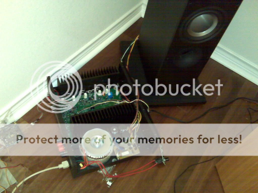
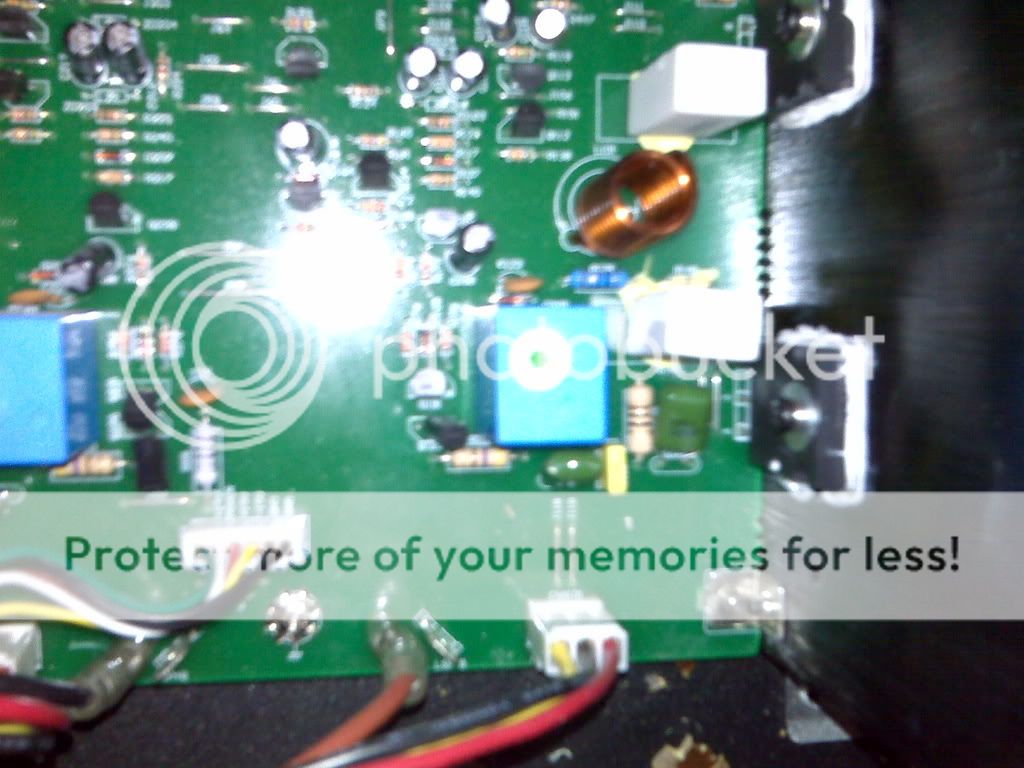
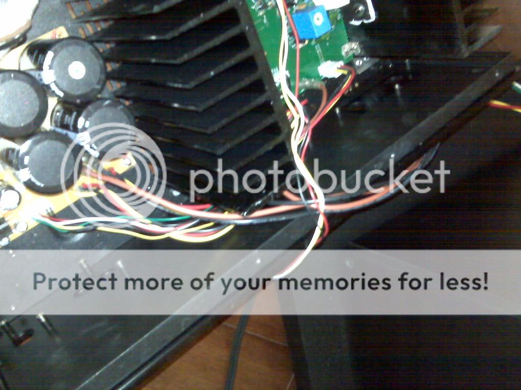
Global view, you can see the line input and speaker out going directly intothe board. The earth leads from the speaker go directly into the power supply board. I am sure there are cleaner ways of doing this, not sure....
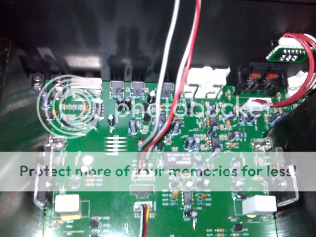
110V AC runnin up the side of the entire PS section, close by the 15V regulators, just so that the ON button can be in the front. Connected to the equally useless 110V/240V selection switch
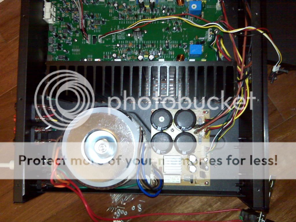
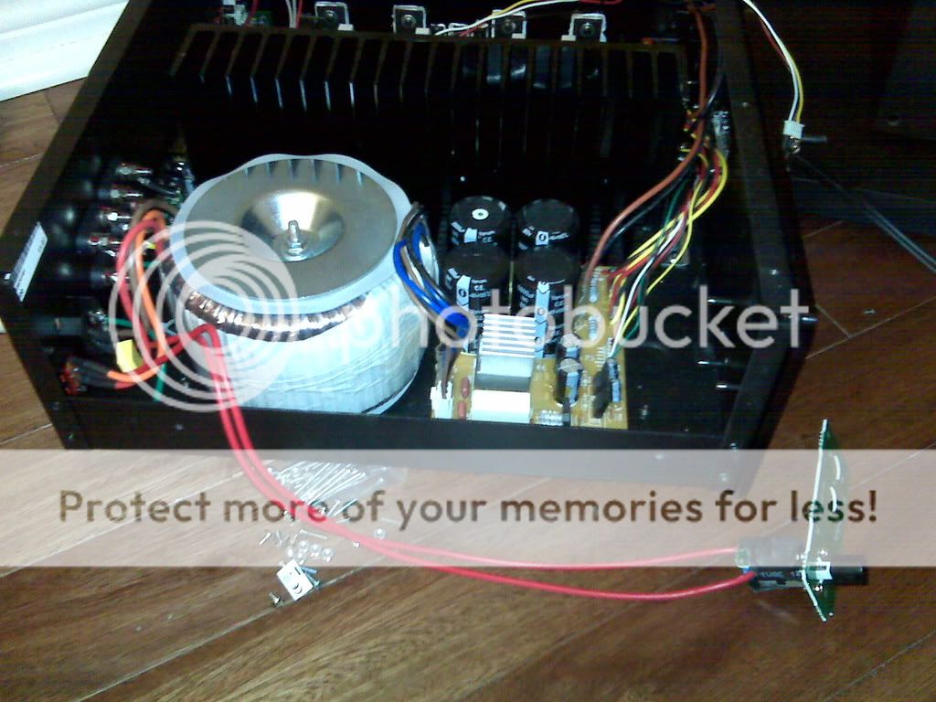
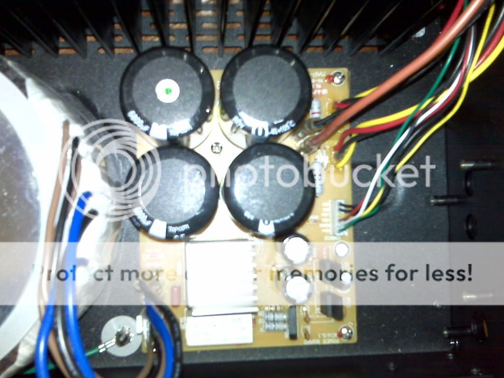
The nice huge transformer next to the inadaquate regulator board, with smallish filter caps. You can see on the left the original location for output to speakers (next to all the high voltage AC stuff). The negative going straight into the PS board. Both the + and - were routed through a speaker selection switch at the other side of the unit, which I have taken out.
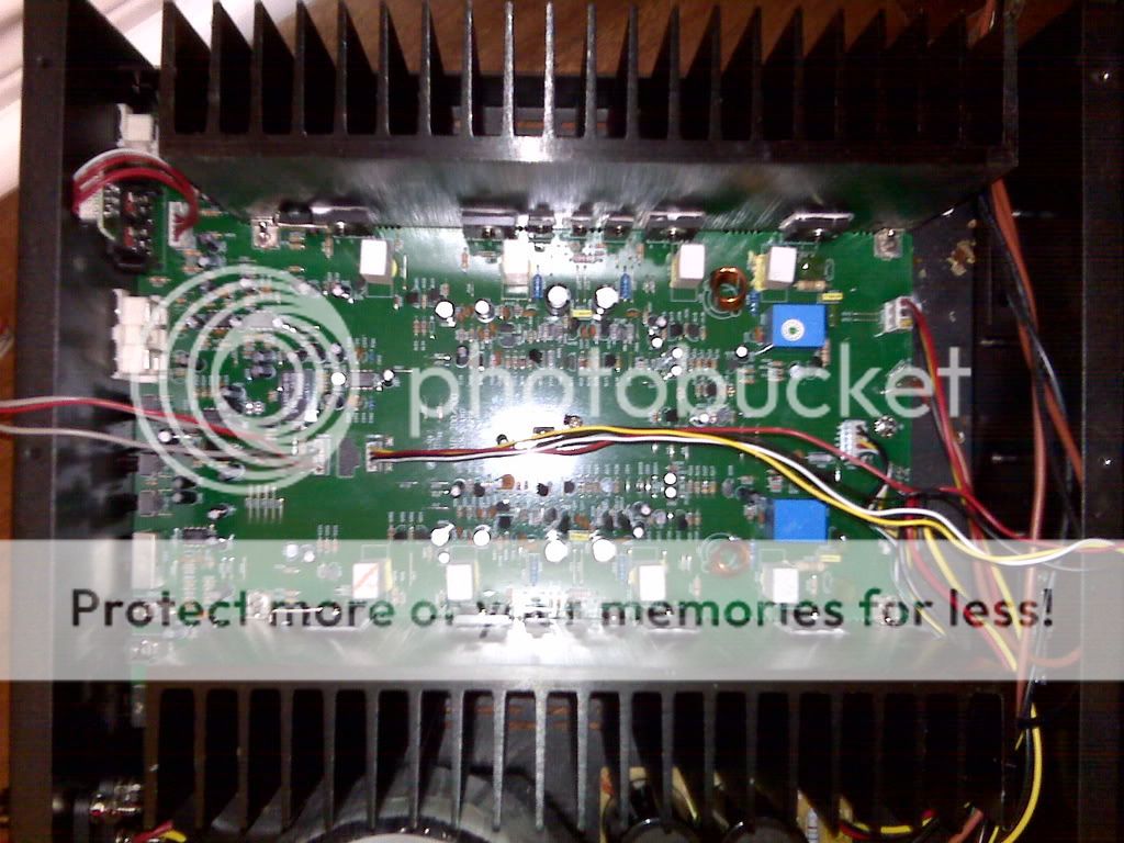
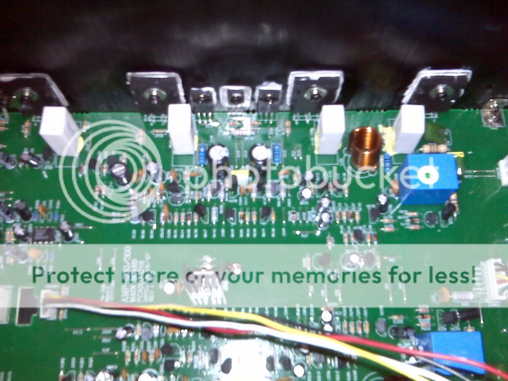
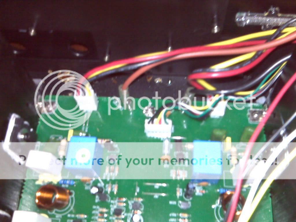
Main board with the bypassed input circuitry on the left (ugly opamps used throughout). The connectors in the middle went to a tone/volume board at the front, and the other was a return. This made it easy to bypass inputs... Also note the mix of main rails, low voltage rails, and speaker leads all routed together and close to the output section. The + lead connection on the board is right next the rail input.
- Status
- This old topic is closed. If you want to reopen this topic, contact a moderator using the "Report Post" button.
- Home
- Amplifiers
- Solid State
- Please explain what I did