Just finished my Pass Pearl built from Promitheus boards and there is a background hum, but worse there appears to be disortion generated from high notes.
I tested all the volatges at the indicated points on the boards and they all check out, at least within 5%-7%.
I though that it may be something else in the system but i ran my turntables signal through a cheap pro-ject phonobox and it is dead quite. What could possibly be causing this weird distrtion and hum from the Pearl?
I have attached images of the boards.
Again, as always, help would be greatly appreciated.
Cheers
Neil
neil_kaye :
Actually i tried to place torrid close to mainpcb, back when i was making my pearl, and anything near < 20cm, was giving me noise and stuff like that. I never tried to attach a metalplate between torrid and pcb through, i simply plugged the psu in another cabinet.
Actually i tried to place torrid close to mainpcb, back when i was making my pearl, and anything near < 20cm, was giving me noise and stuff like that. I never tried to attach a metalplate between torrid and pcb through, i simply plugged the psu in another cabinet.
Hi,
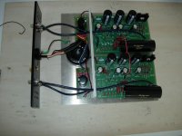
Having read through some other threads i suspect it may be a grounding problem. The way i have ground the project is as follows:
1. From the central ground point on each board (arrow on board which says connect grounds here) i have run a wire to a chassis star ground- see two red wires in photo.
2. From this point there is a direct ground wire to the AC earth / ground
I think the distortion might be from cross talk, would someone please let me know how they succesfully wire their Pearl or please comment on my wiring stradegy.
All my internal wires are shielded.
I have tested the board with different cartridges the the problem of distrortion and hum persist.
The chassis itself is 1/4" aluminum plate so no chance of components picking up interefance through that and the trafo is seperated from the boards with a 1/4" plate .
Thanks for the help
I have tested the votlages and this is waht i get. Both channels are identical:
DC In: 49.7V
R8: 28.3V (29V = 2.5% deviation)
Q3: 23.9V (24.6V = 3% deviation)
Q4: 13.2V (13.8V = 4.5% deviation)
Q5: 10.9V (11.7V = 7% deviation)
These numbers seem pretty good but still the hum persists and there is also a high pitch whine. Ughhh
DC In: 49.7V
R8: 28.3V (29V = 2.5% deviation)
Q3: 23.9V (24.6V = 3% deviation)
Q4: 13.2V (13.8V = 4.5% deviation)
Q5: 10.9V (11.7V = 7% deviation)
These numbers seem pretty good but still the hum persists and there is also a high pitch whine. Ughhh
neil_kaye said:
The chassis itself is 1/4" aluminum plate so no chance of components picking up interefance through that and the trafo is seperated from the boards with a 1/4" plate .
Thanks for the help
1/4" aluminum is not neseccerely enough to keep the trafo from interfering with the circuit. You have also got your in and out running past the trafo, which is sure not a good idea.
Try moving the trafo a couple of feet away from the circuit and see if that helps.
Magura
")
neil_kaye said:I have tested the votlages and this is waht i get. Both channels are identical:
Your post crossed mine.....
If the hum is also identical on both channels, you can be sure it's either a ground issue, which I see no reson you should have in your setup, or its the trafo being too close to something.
Magura
neil_kaye said:At this point i am certain you are correct. Before i dis-assemble everything i was wondering if you know of an off the shelf product that would shield the transformer in its current posistion?
Not really, depending how big the problem is you could maybe get away with a thick box of aluminum, but when I say thick I mean like 1"

Keep in mind that it must be a box covering the entire trafo to really work.
My recommendation would be in direction of making a seperate PSU like most other Pearl builders have done.
Magura
From your photo, we can see that the transfo is really close to the most sensitive part of the PCB, the input. You should at least try to rotate the PCB and mount the input on the front and the output on the back, near the transfo. Don't let the input floating when doing your test, try to short them and see if the noise is gone. My own Pearl is all assembled now and working.
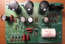
One suggestion, install a tie-wrap to hold tightly to the PCB your big output capacitor. These big caps are really microphonic and need some damping. You may also insert some foam layer under the cap before putting the tie-warp. See my own pcb image for an example.
Send me an email. I'll send you my own PCB voltages.
Bye.
Attachments
I just remember. I had exactly the same problem with my ONO phono preamp. It was one of the fet quad that was defective. Check if the noise is coming from just one channel. Insure also that all quad fet resistors are reading about the same voltages. It should be around 120mv.
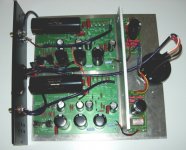
Thanks for all the great responses. I am currently making the following adjsutments and will post photo's and results as soon as i finish it up:
1. Rotate the boards and layout so the Line in's don't cross thhe transformer.
2. This places the outs immediatley adjasent to the RCA's which eliminates several inches of internal chassis wiring.
3. Shield the AC line and ground shield to earth.
4. Move the traffo further away from the boards. I am tight on space but the few inches might help.
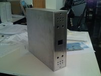
5. For the fun of it i am building an internal chassis enclosure for the toroid. A 1/4" ring of alumuinum pipe and cover plate wrapped on the inside and outside with copper foil.
6. Try to stabalize the capacitors.
The photo does not show the toroid shield yet (should eb completed by the end of the week) but indicates the new layout
Thanks
Neil
1. Rotate the boards and layout so the Line in's don't cross thhe transformer.
2. This places the outs immediatley adjasent to the RCA's which eliminates several inches of internal chassis wiring.
3. Shield the AC line and ground shield to earth.
4. Move the traffo further away from the boards. I am tight on space but the few inches might help.
5. For the fun of it i am building an internal chassis enclosure for the toroid. A 1/4" ring of alumuinum pipe and cover plate wrapped on the inside and outside with copper foil.
6. Try to stabalize the capacitors.
The photo does not show the toroid shield yet (should eb completed by the end of the week) but indicates the new layout
Thanks
Neil
Attachments
Err, you do understand that you need an metallic enclosure for the full phono pre (not just around the trafo)?
Otherwise you're just receiving RF-noise and that is hundreds of times louder than any vibrating capacitors or trafo noise.
Maybe I'm missing something here, but from the photo this is obvious.
All the best, Hannes
Otherwise you're just receiving RF-noise and that is hundreds of times louder than any vibrating capacitors or trafo noise.
Maybe I'm missing something here, but from the photo this is obvious.
All the best, Hannes
I see you still have the input stage of the Pearl closest to the toroid. That was one of the things most recommended above. Move the phono boards so the input side is furthest from the tranny. I think you should worry less about the AC line ins than the magnetic flux that the torroid throws out.
I had a question for others who have built the Pearl with an external power box: Do you tie the ground of the Pearl chassis to the chassis ground of the power supply? Also, do you connect the tonearm ground plug to the same star ground that the boards are hooked to?
I had a question for others who have built the Pearl with an external power box: Do you tie the ground of the Pearl chassis to the chassis ground of the power supply? Also, do you connect the tonearm ground plug to the same star ground that the boards are hooked to?
- Status
- This old topic is closed. If you want to reopen this topic, contact a moderator using the "Report Post" button.
- Home
- Amplifiers
- Pass Labs
- Distortion and hum with Pearl