Hi Folks,
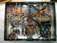
For anyone following my journey towards completing my first project, here is a shot of my progress so far with the wiring almost complete.
I have just discovered an unbelievably stupid, show-stopping mistake. I thought I would post it for entertainment value. My mistake can clearly be seen in the photo and is not subtle (not dangerous either) but the amp is not going to do anything till I fix it up. Can anyone spot it?
I will post the answer with a picture illustrating the solution when I have fixed it up. I will then be ready for power up and I will post a follow up report with some shots of the completed amp.
Cheers,
Rob
Attachments
Yo Rob,
That's a very nice layout and wiring job indeed. After studying the picture, the main thing I would not have done is to use RCA phono jacks for the speaker connections. I like 5-way binding posts or BIG screw type barrier blocks. Phono jacks and plugs are just not compatible with todays hefty speaker cables. Otherwise, it looks great!
Victor
Where are the speaker connections? LOL They appear to be inside the amplifier well outside of reach if I'm not mistaken..
One other thing I think I noticed is that the output transformer primaries are going to barrier strips - they really ought to go directly to the correct output tube socket plate and screen grid connections. The voltages present on these connections during normal operation are up to 2X your supply voltage and 180 degrees out of phase from one side to the other and may result in arcing and other excitement. I'd recommend series resistors of at least 220 ohms at the screens for good stability as well. (Up to 1K is not unusual) Sometimes the extra length of wire running around in the chassis will result in vhf oscillations in the screen circuit. Puzzling to troubleshoot if you don't have a fast scope and haven't seen this before.
One other thing I think I noticed is that the output transformer primaries are going to barrier strips - they really ought to go directly to the correct output tube socket plate and screen grid connections. The voltages present on these connections during normal operation are up to 2X your supply voltage and 180 degrees out of phase from one side to the other and may result in arcing and other excitement. I'd recommend series resistors of at least 220 ohms at the screens for good stability as well. (Up to 1K is not unusual) Sometimes the extra length of wire running around in the chassis will result in vhf oscillations in the screen circuit. Puzzling to troubleshoot if you don't have a fast scope and haven't seen this before.
Kevin & SY,
I copied the picture to my desktop and then opened it with MS photo editor in Office. (Other programs could be used) Then I lightened it up and magnified it. You can clearly see a length of shielded cable connecting the phono jacks to the speaker terminal blocks. Those blocks should be on the rear apron instead of inside. Agreed on the excessive lenght of the primary leads also.
The black thing below the power transformer looks like a three prong receptacle that contains either a switch or a fuse. It looks like the ground wire is coming from the end connection. But he said it wasn't a dangerous error. Perhaps things are different down under.
Victor
The Answer
Hi again,
The feedback I get here is great and will be invaluable for my next project. I think I need to clarify a few things first -
1. The speaker jacks are for RCA plugs and are located on the outside of the chassis!
2. My terminal blocks are rated at 1000v, so I am hopeful that they will be OK
3. The black plastic box just behind the transformer is a power cord plug with integrated fuse and mains switch.
4. The safety earth is properly wired up and bonded to the chassis with non-slip washers and lock-tite.
Now for the howler -
I decided to have a switch on the front (seen top left, separate from the mains switch on the back). Even though the switch is rated to 240v, I did not want to run 240v power to the front of the amp for fear of increasing hum. To 'solve' the problem, I have run the active mains into a solid state relay (the small black rectangle bottom left) before it hooks up to the power transformer. The relay trigger is a rectified current form the 6.3 v heater wiring. This system worked beautifully on the bench with an external power supply. Herein lies the problem; The relay relies on the 6.3v from the transformer and the transformer won't get the mains supply until the relay is triggered. Catch 22. No one should feel that they need to comment on the stupidity of this, I have acute self-awareness
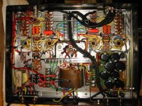
Anyhow, find attached the (simple) solution. If anyone can think of a better one, I would be grateful.
Almost ready for first test!! Will report back soon.
Cheers,
Rob
Hi again,
The feedback I get here is great and will be invaluable for my next project. I think I need to clarify a few things first -
1. The speaker jacks are for RCA plugs and are located on the outside of the chassis!
2. My terminal blocks are rated at 1000v, so I am hopeful that they will be OK
3. The black plastic box just behind the transformer is a power cord plug with integrated fuse and mains switch.
4. The safety earth is properly wired up and bonded to the chassis with non-slip washers and lock-tite.
Now for the howler -
I decided to have a switch on the front (seen top left, separate from the mains switch on the back). Even though the switch is rated to 240v, I did not want to run 240v power to the front of the amp for fear of increasing hum. To 'solve' the problem, I have run the active mains into a solid state relay (the small black rectangle bottom left) before it hooks up to the power transformer. The relay trigger is a rectified current form the 6.3 v heater wiring. This system worked beautifully on the bench with an external power supply. Herein lies the problem; The relay relies on the 6.3v from the transformer and the transformer won't get the mains supply until the relay is triggered. Catch 22. No one should feel that they need to comment on the stupidity of this, I have acute self-awareness
Anyhow, find attached the (simple) solution. If anyone can think of a better one, I would be grateful.
Almost ready for first test!! Will report back soon.
Cheers,
Rob
Attachments
Rob,
Awesome job on the amp, can we see a top view of the amp..
As all of us DIY'ers, we all can admit to a "what a freaking idiot thing I did"
When I built my 1st nixie clock using all TTL chips, 17 in all (http://www.tuberadios.com/nixie/) I laid out the chips on the circuit board and one by one I wired all the chips together, then I noticed, with the circuit board upright my clock would have told time SS:MM:HH instead of HH:MM:SS... DUH, hence all the wires on the top edge of the circuit board crossing from one side of the board to the other...
Regards,
Sal Brisindi
Thanks Sal,
I feel a little bit better. Hi Charlie, the pot looked as if it was backwards to me as well but it is OK. I understand now about the terminal blocks and the RCA plugs. I have never owned speakers which were good enough to worry about cables that could not cope with RCA plugs.
Another small clarification, the mains power socket at the rear of the unit has the plug aligned vertically. The earth is OK. I will post some external shots soon, hopefully with some good news ie I hope it works!!!
Thanks for the comments.
Rob
As all of us DIY'ers, we all can admit to a "what a freaking idiot thing I did"
I usually have that revelation as the smoke cloud rises slowly to the ceiling. There is a toasted $7 mosfet sitting next to my keyboard to remind me of last weeks "oops".
Notes:
Mosfets don't live long when inserted into the PC board backwards. They smoke when 450 volts is applied to the gate!
- Status
- This old topic is closed. If you want to reopen this topic, contact a moderator using the "Report Post" button.
- Home
- Amplifiers
- Tubes / Valves
- 1st Time Project - Spot the howler