Hi. Just tought it might be interesting to post about a TDA2050 amp I just built.
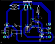
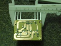
I still have to test it to know exactly how well it is working, but I was already able to listen to Discharge and nag my neighbours... I'm sending the eagle lay-out, but I used it only for drilling / punching the holes. I drew the board by hand, and the power tracks are about 5mm thick.
I used a 1A +-15V power source, and a feeble oval speaker savaged from a computer "multimedia" amp. Pictures coming soon!...
Attachments
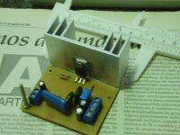
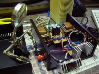
Finally I got my camera back... Here are some (ugly!) pics of the amp. ")
The design is basically the one suggested on the datasheet. I just redraw to remove thas space for the stuff that you might use on the TDA2030.
Caps are 16v... I also changed the type of the input capacitor because it makes me nervous to use electrolytics there
Yes, I decided to drill the holes after, and then decided I did need them!
Attachments
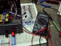
"Smoke test" of the PSU. Some serious 2.46 ampères going on! Almost 10W on "big green" 1.5 ohms load. The heatsink is too small for that... The voltage on the regulator input is 20V, with a 5V output so it means 15*2.46 = around 37W  It was almost too hot for touch (probably would be with both regulators on!)
It was almost too hot for touch (probably would be with both regulators on!)Attachments
- Status
- This old topic is closed. If you want to reopen this topic, contact a moderator using the "Report Post" button.
- Home
- Amplifiers
- Chip Amps
- TDA2050 success story