Greetings to everyone,
I want to know if it's possible to make amplifier with a bridge topology for single supplies without using two distinct amplifiers.
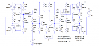
I've this schematic from LTSpice examples, but I want to know if it's possible to make something with better specs, using current sources, an enhanced current mirror at the IPS output to increase the open loop gain and also a beta enhanced VAS or a differential VAS. I've tried to do such thing but the amplifier saturates, I can't set the DC value at the outputs, the amplifier outputs stays at Vcc-Vsat or Vsat.
Best regards,
Daniel
I want to know if it's possible to make amplifier with a bridge topology for single supplies without using two distinct amplifiers.
I've this schematic from LTSpice examples, but I want to know if it's possible to make something with better specs, using current sources, an enhanced current mirror at the IPS output to increase the open loop gain and also a beta enhanced VAS or a differential VAS. I've tried to do such thing but the amplifier saturates, I can't set the DC value at the outputs, the amplifier outputs stays at Vcc-Vsat or Vsat.
Best regards,
Daniel
Attachments
Good idea
Hi Daniel, it is definitely possible.
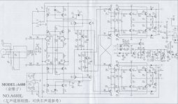
Here is a very good example - Accuphase A680 (see attached schematic).
Symmetric input stage, then mirrored common base VAS. Each side of it works on separate drivers and OPs.
Two DC offset integrators, 2 global NFB loops, balanced input.
Extremely elegant...
Cheers,
Valery
Hi Daniel, it is definitely possible.
Here is a very good example - Accuphase A680 (see attached schematic).
Symmetric input stage, then mirrored common base VAS. Each side of it works on separate drivers and OPs.
Two DC offset integrators, 2 global NFB loops, balanced input.
Extremely elegant...
Cheers,
Valery
Attachments
Hi Valery and thanks for your help,
Very interesting circuit.
But it seems very complicated.
It's not possible to make something a little bit more simple?
An amplifier like this has to use DC servos (integrators) to ensure DC stabilization? Or they're optional?
Best regards,
Daniel
Very interesting circuit.
But it seems very complicated.
It's not possible to make something a little bit more simple?
An amplifier like this has to use DC servos (integrators) to ensure DC stabilization? Or they're optional?
Best regards,
Daniel
Hi Valery thank you once more for your help,
Do you know why this amplifier (attached) have DC stability problems, I can't stabilize the output at Vcc/2, can you help me here?
PS: It's possible to use a differential VAS and use both legs of the VAS to connect the two OPSs?
Or it's a bad idea?
Best regards,
Daniel
Do you know why this amplifier (attached) have DC stability problems, I can't stabilize the output at Vcc/2, can you help me here?
PS: It's possible to use a differential VAS and use both legs of the VAS to connect the two OPSs?
Or it's a bad idea?
Best regards,
Daniel
Attachments
Last edited:
Tricky servo
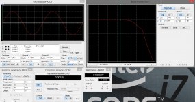
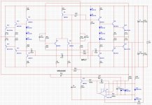
Here we go
Sorry - could not avoid DC servo here.
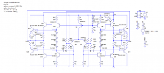
The problem is that in such a bridged design it is important to stabilize the DC parameters and the best way to do it I see at the moment is to stabilize the LT current via DC servo with open collector, controlling long tail. When it is stabilized this way, all queiscent currents are set and the outputs are balanced between the rails. It is possible to do it manually with a trimmer, but because of temperature changes, elements tolerance, etc. it will not be stable. Integrator provides auto-balancing.
I have also played with some values - not important.
Result - a decent amp, self-balanced, stable, pretty efficient for such a simple design.
I had to artificially ground one of the outputs - otherwise multisim's THD meter does not work (rather inconvenient) - in real prototype the ground would be between the power sources.
By the way, now it is easy to use a single power source if you like - just set the point marked GROUND between the rails (couple of resistors with filtering caps) - DC servo will balance the scheme automatically.
Appeared to be an interesting project in the end
Let me know if you need more explanations.
Cheers,
Valery
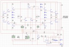
P.S. You can try differential VAS - it will work even better. But DC servo will still be required if you want auto-balancing feature.
Here we go
Sorry - could not avoid DC servo here.
The problem is that in such a bridged design it is important to stabilize the DC parameters and the best way to do it I see at the moment is to stabilize the LT current via DC servo with open collector, controlling long tail. When it is stabilized this way, all queiscent currents are set and the outputs are balanced between the rails. It is possible to do it manually with a trimmer, but because of temperature changes, elements tolerance, etc. it will not be stable. Integrator provides auto-balancing.
I have also played with some values - not important.
Result - a decent amp, self-balanced, stable, pretty efficient for such a simple design.
I had to artificially ground one of the outputs - otherwise multisim's THD meter does not work (rather inconvenient) - in real prototype the ground would be between the power sources.
By the way, now it is easy to use a single power source if you like - just set the point marked GROUND between the rails (couple of resistors with filtering caps) - DC servo will balance the scheme automatically.
Appeared to be an interesting project in the end
Let me know if you need more explanations.
Cheers,
Valery
P.S. You can try differential VAS - it will work even better. But DC servo will still be required if you want auto-balancing feature.
Attachments
Last edited:
I want to know if it's possible to make amplifier with a bridge
topology for single supplies without using two distinct amplifiers.
Daniel
Hi,
Possible, but hopelessly inaccurate AFAIK. The implication is
only one feedback loop, which cannot set the dc conditions.
If it could be done, it would be common, it isn't, it can't.
Car stuff has exploited every single supply option available.
rgds, sreten.
The implication is
only one feedback loop
Hi sreten, you can always use two feedback loops in bridged designs.
Then you have to solve a DC stability issue, but here an integrator is your friend (as one of possible solutions).
Regards,
Valery
could also read up on fully diferential I/O op amps - which do have a common mode control loop built in
the common mode loop can be very nearly orthognal to the differential gain - very little interaction between the two
Pass SuSy may also illustrate an option for "integrated" bridging
the common mode loop can be very nearly orthognal to the differential gain - very little interaction between the two
Pass SuSy may also illustrate an option for "integrated" bridging
I just roughly chose the queiscent currents for each stage - 1mA per LTP output (2mA for the long tail), 10mA for VAS and 100mA for the OP. Then I reduced R1, R2 and R7, R8 respectively to increase VAS gain, allowing lower distortion via deeper global NFB. Gain increase required more comprehensive compensation.
C5 between the LTP outputs is a so called lag compensation cap. Actually, this design will work without it, but you will find some signs of oscillation (not criminal, but still) after a fast front, at square wave for example. With C5 in place square wave is nice and clean.
Yes, DC offset at both outputs very much depends on IPS current, so DC servo compares it to the point between the rails and regulates, keeping the output offsets equal to that point. It is a very accurate self-balancing "mechanism". LF411 is very good for this purpose due to low input currents and low-drift design in general. I invented the way of driving the IPS current with "open collector" just yesterday, thinking about your design.
Thank you for inspiration
Pass shows at least one amplifier that runs off single polarity supply and yet has balanced output for the speaker load.I want to know if it's possible to make amplifier with a bridge topology for single supplies
Hi Valery and thank you for your great help and support,
I don't know if I will build this amplifier later, it seems very interesting indeed. But now I want to make something more simple with single ended output, do you recommend me a simple CFA design like VSSA, or it's better to make a simple VFA design?
Why that bridge amplifier from LTSpice exemples, attached to the first post works without an integrator?
Best regards,
Daniel
- Status
- This old topic is closed. If you want to reopen this topic, contact a moderator using the "Report Post" button.
- Home
- Amplifiers
- Solid State
- Bridge Amplifier