in an older sub-thread, Sherman described a method for using a center tap transformer with two bridges. he made it with the briangt pcb kit. the described circuit is illustrated below, and it doesn't work because PG- and PG+ connect at the power star: AC1 and AC2 short. which is indeed what Steve found when he tried to follow Sherman's directions.
yet Sherman got it going somehow. it seems there must be missing information. does anyone know what that would be?
the sub-thread,
#386
http://www.diyaudio.com/forums/showthread.php?postid=380876#post380876
#402
http://www.diyaudio.com/forums/showthread.php?postid=382085#post382085
#414
http://www.diyaudio.com/forums/showthread.php?postid=382245#post382245
#425
http://www.diyaudio.com/forums/showthread.php?postid=383366#post383366
#444-#455
http://www.diyaudio.com/forums/showthread.php?postid=388348#post388348
#464
http://www.diyaudio.com/forums/showthread.php?postid=393148#post393148
and elsewhere
http://www.diyaudio.com/forums/showthread.php?postid=598279#post598279
http://www.diyaudio.com/forums/showthread.php?postid=548382#post548382
i've wondered if Sherman has flipped some diodes around on the pcb, instead of orienting them all in the same direction. perhaps it's possible to end up with what's essentially a single bridge CT circuit with some harmless run-around between the 'halves' of the bridge, but i haven't figured a combination that does that.
so, i'm dry of ideas. can someone else solve the mystery?
thank you lilolee, but i'm afraid this is not the same thing.
the ESP circuit is running parallel bridges; one bridge per channel. the circuit i am describing does not have this separation. the briangt is series bridges that supply both channels. PG- and PG+ meet at the ground star of each channel.
Sherman's description and his drawings do not indicate he has changed this to one bridge per channel. he shows all lines from bridge PCB to channel PCBs as parallel.
Sherman wrote the following
I have built a few power supplies with 2 bridges using CT transformers. It does seem to matter how you use the CT though. It would seem that (using the Brian GT boards nomenclature) you would wire one AC line to AC1H and the other to AC2H and then use the CT for AC1N and AC2N. When I tried that I blew fuses.
What I found that has worked for me is this-
AC1 from the transformer to AC1H on the board
CT from the transformer to AC1N on the board
CT from the transformer to AC2H on the board
AC2 from the transformer to AC2N on the board
diagram here
lilolee said:Sherman wrote the following
What I found that has worked for me is this-
AC1 from the transformer to AC1H on the board
CT from the transformer to AC1N on the board
CT from the transformer to AC2H on the board
AC2 from the transformer to AC2N on the board
yes. this is what i have drawn.
diagram here
yes. this illustration shows parallel leads after the bridge PCB.
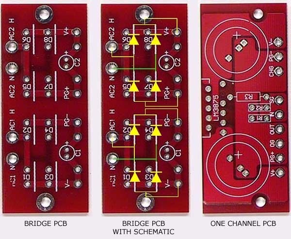
below is the PCBs in question. i have overlain the bridge schematic on a duplicate bridge image. there are two independant bridges with dual outputs. all four outputs go to each channel PCB as the illustration you have linked shows. then on the channel PCB you see PG+ and PG- join at the same ground. so these bridges are in series.
the ESP drawing is of parallel bridges; one per channel.
i'm afraid i do not see what you are trying to point out to me. this is a most uncomfortable feeling.

yes. that circuit should not work. that is indeed the point.
as i said in my opening post, this should not work. the curiosity is that this is what Sherman describes in detail, and at some length, as working for him. as i said, there must be missing information: something must be different in Sherman's actual arrangement that he did not see.
which is pretty odd, because there is not much to see.
we know he has a CT tx. we know there are eight diodes on the briangt bridge PCB. we know that four wires go from the bridge PCB to each channel PCB. we know PG- and PG+ meet on the channel PCBs.
which means this circuit pops the fuse or releases the magic smoke. yet his didn't. instead it powered his gainclone.
my best guess is he's done something odd with the arrangement of the diodes and gotten some sort of single bridge functioning out of it, but danged if i can replicate that either.
hence my question is, what did he do?
rest assured, i'm not asking how to make a series bridge arrangement work with a CT tx. you can't.
it just works
if i'm not mistaken, there is nothing wrong with the circuit.
like lilolee mentioned,
AC1 from the transformer to AC1H on the board
CT from the transformer to AC1N on the board
CT from the transformer to AC2H on the board
AC2 from the transformer to AC2N on the board
the above should just work.
let's say you have a 20/0/20 supply.
first 20-0 will be rectified to something like 28vdc, measured from V- and PG-.
second 20-0 will give 28vdc, measured from V+ and PG+.
PG- and PG+ would be the 0 in +28/0/-28vdc. V+ being the positive 28 and V- being the negative 28.
I've not built the circuit, but I did try simulating it by chance when investigating power supplies a while ago. I got output from it but the ripple on the lines was far worse than acceptable from other configurations.
garbage, PG- and PG+ meet at the channel PCB. hence AC1 meets AC2. also, AC1 meets CT, and CT meets AC2 -- all tx lines are shorted together when you join PG1 and PG2.
the circuit becomes identical to laying a diode from AC1 to CT, and a second diode from CT to AC2.
the circuit becomes identical to laying a diode from AC1 to CT, and a second diode from CT to AC2.
ofb said:garbage, PG- and PG+ meet at the channel PCB. hence AC1 meets AC2.
ofb
at the risk of sounding silly if i missed some fundamentals of hooking up this CT supply...
PG- and PG+ are meant to meet. it forms the 0 for the +28 and -28vdc after rectification.
with a transformer that has 20/0/20 winding, from your bridge pcb with schematic image, you should get:
AC1N and AC1H fed with one pair of 0-20 vac winding.
AC2N and AC2H fed with another pair of 0-20 vac winding.
PG- and V- (measures -28vdc with red probe at PG- and black probe at V-)are the rectified voltage outputs of AC1N and AC1H.
PG+ and V+ (measures +28vdc with red probe at V+ and black probe at PG+)are the rectified voltage outputs of AC2N and AC2H.
V+ and PG- or PG+ gives +28vdc for the positive rail of a GC and
V- and PG- or PG+ gives -28vdc for the positive rails of a GC.
PG- and PG+ meeting together is intended as it forms the 0vdc or ground point for the rails to be referenced to. measuring V+ and V- should give 56vdc for this example.
do note that all grounds on the briangt pcbs are connected.
i just did a search here... take a look at post #6 of this thread for a clearer view of configuration of the transformer.
ps, what is the transformer that you have?
cheers
garbage
garbage,
I think you need to look more closely at the secondary side of the bridges... specifically tracing the route of currents and seeing how far they can travel around...
I think you need to look more closely at the secondary side of the bridges... specifically tracing the route of currents and seeing how far they can travel around...
richie00boy said:
I think you need to look more closely at the secondary side of the bridges... specifically tracing the route of currents and seeing how far they can travel around...
hi richie00boy
i happen to have those pcbs.
on the rectifier pcb, PG+ and PG-, along with V+ and V- are not connected to each other. they just stop dead there. does not travel anywhere else.
but on the LM3875/LM4780 pcb, PG+ and PG- are connected. this forms the 0vdc point for the rails.
maybe i've lost it. 😕
Originally posted by garbage
at the risk of sounding silly if i missed some fundamentals of hooking up this CT supply...
no worries! all this side discussion certainly has me wondering if i'm the one who has lost it. so let's step back and walk through slowly.
PG- and PG+ are meant to meet. it forms the 0 for the +28 and -28vdc after rectification.
yes, PG- and PG+ are meant to meet. but the briangt boards are designed for dual secondaries. with dual secondaries, 2x20 (to stay within your example values), PG+ becomes -28vdc, and PG- becomes +28vdc.
they meet without trouble at the channel PCB because they are on different windings.
not to insult anyone, but maybe i should re-cover a basic?: on dual secondaries, each secondary is a separate wire that coils inside the tx. they do not meet each other. you have four wires with dual secondaries: the the wires are the two ends of the two coils. with a CT, three wires come out of the secondary side, and these all come from a single coil. the CT wire is connected to the middle of the coil and the other two wires are its ends.
you can make a CT tx out of dual secondaries by joining two secondaries. this gives you a single coil with a Center Tap. but you cannot make dual secondaries from a CT tx.
(well, yes you can... sometimes you are lucky and the CT you have is actually made from two coils joined inside the tx. then you can dig in there and carefully separate them and have dual secondaries for your gainclone, but this is not basics anymore. also, as good forum manners i should emphasize: Don't Do This Unless You Absolutely Know What You Are Doing! ... okay, where were we? oh yeah, the basics.)
now, with a CT tx, 20-0-20, you actually don't run the CT into the bridge, you run it past the bridge straight to the power star on the channel PCBs.
back on the first page, lilolee has posted that typical CT circuit.
please do note, and let us not be confused by, the fact that that circuit shows both channels instead of one. in that circuit, both channels use their own bridge: the parallel structure begins at the tx secondaries. although there are two bridges, they are in parallel, which is not the series bridge construction feeding both channels that we are discussing ... i just wanted to emphasize that so we don't fall down that hole again.
i just did a search here... take a look at post #6 of this thread for a clearer view of configuration of the transformer.
matjans is illustrating dual secondaries, not CT.
Originally posted by richie00boy
I think you need to look more closely at the secondary side of the bridges... specifically tracing the route of currents and seeing how far they can travel around...
exactly.
Originally posted by garbage
i happen to have those pcbs.
on the rectifier pcb, PG+ and PG-, along with V+ and V- are not connected to each other. they just stop dead there. does not travel anywhere else.
garbage, richie00boy means follow it around the whole circuit, not just on the bridge PCB. when PG- and PG+ meet, you will see that the tx secondaries short. above, megajocke made a sketch showing two of the three shorts that occur.
ps, what is the transformer that you have?
both. but please, i am not asking how to hitch up a tx. it's kind of you to try to help me with that, but that's actually not a problem, nor is it the subject of this thread. i am only asking what is going on in that curious sub-thread by Sherman.
maybe i've lost it. 😕
hah! by now i am certainly questioning myself! i hope i have not stepped on my own tail here trying to get back to the original question.
and i sincerely hope i have not insulted anyone by going slow with basics. i only did that because it is odd that we are not seeing the same thing, so i figured we best go back to find where we fell out of step.
actually V+(red probe here)/PG+ is +28vdc and PG-/V-(red probe here) is -28vdc.ofb said:
yes, PG- and PG+ are meant to meet. but the briangt boards are designed for dual secondaries. with dual secondaries, 2x20 (to stay within your example values), PG+ becomes -28vdc, and PG- becomes +28vdc.
i finally see what you mean 🙂you can make a CT tx out of dual secondaries by joining two secondaries. this gives you a single coil with a Center Tap. but you cannot make dual secondaries from a CT tx.
[/b]
in this case, i think you are most likely correct. i failed to see this point initially.
you are absolutely right on this.now, with a CT tx, 20-0-20, you actually don't run the CT into the bridge, you run it past the bridge straight to the power star on the channel PCBs.
[/b]
no worries, i certainly learnt from this. 😉hah! by now i am certainly questioning myself! i hope i have not stepped on my own tail here trying to get back to the original question.
and i sincerely hope i have not insulted anyone by going slow with basics. i only did that because it is odd that we are not seeing the same thing, so i figured we best go back to find where we fell out of step.
[/b]
if i'm not mistaken on this, alternatively, if you have 10/0/10 and another 10/0/10 winding on the transformer, you'd be able to use the each 10/10 winding as a 20vac winding (leave the CT unconnected) and connect normally to AC1N/AC1H and AC2N/AC2H.
cheers
garbage
This topic has been already discussed some time ago and there is no way for this arrangement to work. The only solution is to split the center tapped windings.
Originally posted by garbage
actually V+(red probe here)/PG+ is +28vdc and PG-/V-(red probe here) is -28vdc.
yup. the way the diodes are arranged, the DC current goes out the V+ and in the PG+, and vice versa on the other bridge. hence i stated it the way i did. you're measuring voltage and direction across the two points; i was talking about the individual PG points, and indicating the current direction across the points. ie, at PG+ you have 28v inbound to the bridge, and at V+ that 28v is outbound. s'all good, it just depends on your reference point: where you put the black probe.
if i'm not mistaken on this, alternatively, if you have 10/0/10 and another 10/0/10 winding on the transformer, you'd be able to use the each 10/10 winding as a 20vac winding (leave the CT unconnected) and connect normally to AC1N/AC1H and AC2N/AC2H.
yup, you can certainly do that. that'd cause no problem except perhaps RF interference? it might act as an emitter or receiver of junk? that's beyond me, but i think i'd make the unused CT short to be sure.
while you're thinking about these things, here's a question: what if you only use one of the two windings? there is no flow through the second winding, but it's still a coil around a fluctuating magnetic field. does it present a load on the tx in any way?
for the record, probably not, because a number of people here have used just one coil of two and no-one has spoke up to warn them against it. but still i can't quite visualize it to my satisfaction. this takes me back to my old physics instructor trying to explain the right hand rule to us, and i just can't remember if the coil is still a coil if the ends aren't connected. -- you've got the changing magnetic field, you've got electrons in the coiled wire, so they must be moving back and forth somewhat, wouldn't they? bunching up at one end then the other? if so, what's the load on the tx then?
alongside, say that 2x10 is 50va, and you only use one secondary. is it still 50va?
Eva said:This topic has been already discussed some time ago and there is no way for this arrangement to work. The only solution is to split the center tapped windings.
yes Eva, indeed i did say this will not work.
the question is what did Sherman do that made him think he had series bridges working with his CT tx.
this is all in my original post.
afaik my actual question has not been discussed. i certainly searched.
So in other words we need to have a 25-0-0-25 transformer or implement the ESP circuit.
I have to admit I done exactly the same searches before and never came up with a way. But then my use was slightly different.
Good Luck
I have to admit I done exactly the same searches before and never came up with a way. But then my use was slightly different.
Good Luck
lilolee said:So in other words we need to have a 25-0-0-25 transformer or implement the ESP circuit.
I have to admit I done exactly the same searches before and never came up with a way. But then my use was slightly different.
a way to run series bridges with a CT tx? alas no, this cannot be done.
however, trying to do it is a very good exercise to get PSU basics straight in one's head. 😉
Good Luck
thank you. hopefully someone will indeed see and discuss the actual question at some point.
- Status
- Not open for further replies.
- Home
- Amplifiers
- Chip Amps
- Sherman & the Center Tap Mystery