Hello.
I use amps with TA3020 V2a and a V2b boards from connex.
http://connexelectronic.com/wp-content/uploads/2017/08/TA3020_Audio_Amplifier_Module_v2.pdf
I have 2 questions, maybe you can help me.
I mailed connex 10 days ago, but didn´t get an answer.
I have tried it once more today.
1:
I inspected the boards and noticed a burnt C on the underside of the V2a board. I want to replace it. But it is not numbered an not specified in the schematic.
Anybody know the value of this C ?
I attached a picture of the board and the burnt C.
2:
Setting gain factors.
The boards have different gain (V2a has apr. 8dB more gain). I´d like to set them to the same gain.
The manual says "changing the value of the resistorsR16,andR19."
edit:
The manual numbers are wrong.
see my answer #7
Michael
Attachments
Last edited:
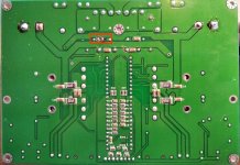
Another top and bottom view, to locate the broken C.
I´m not good at reading/understanding those layouts.
But as far as I can see, the broken C sits on the V- line with C19 and R22 on the underside. But I can´t see the other connection that pulls through to the topside.
I´m not good at reading/understanding those layouts.
But as far as I can see, the broken C sits on the V- line with C19 and R22 on the underside. But I can´t see the other connection that pulls through to the topside.
Attachments


I removed the C from the other line and measured it to be 100nF.
So I´ll just put a new 100nF in.
The only question left is th gainfactor now.
I think the R-numbers in the text and in the schematic are mixed up or not belonging together.
Anybody know which resistors I need to change ?
So I´ll just put a new 100nF in.
The only question left is th gainfactor now.
I think the R-numbers in the text and in the schematic are mixed up or not belonging together.
Anybody know which resistors I need to change ?


burned C probably one of the zobel network capacitors C6 , C14 . C16 or C12 in the datasheet . 100nF as it seems connected to the output after the coil .
Cheers ,
Rens
Cheers ,
Rens
Hi Rens.
Thank you for the answer.
I´ll check that, when I´m back at home.
As far as I can see, the burnt C is in the V+ and V- line.
Because it is connected to the +/- of the big 10.000uF C and to C19+R22 / C2/R3
This is a picture of the other board. (easier to see without the smoke on the pcb)
Thank you for the answer.
I´ll check that, when I´m back at home.
As far as I can see, the burnt C is in the V+ and V- line.
Because it is connected to the +/- of the big 10.000uF C and to C19+R22 / C2/R3
This is a picture of the other board. (easier to see without the smoke on the pcb)
Attachments

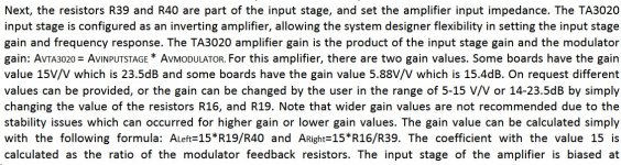
I think I understand the gain setting now.
I think Connex just changes Avinputstage. So it´s RF/RI and Connex just changes RF. RF should be R20 in the connex layout.
The Avmodulator part is the factor 15 in the connex text and therefor doesn´t matter for me.
I corrected the numbers of the input stage in the connex text how I think they should be (just for the input stage of one channel)
So: I think I should just change R20 (and R23) for setting the gain in the input stage.
Can anybody confirm this ?
I´ll check the R20 values on my V2a and V2b board and see if they differ.
Attachments


Last edited:
Umm .. R's 5, 6, 15, and 16 have nothing to do with gain -- they're 'Gate stopper's controlling the MOSFET turn-on behavior. The different values (5R6 and 27R if I'm following correctly) would be needed for different p/n's.
R19 is the Gate pull-down for Q4 (sinking device, ch 1). It assures full turn off since the turn-off diode can't take it all the way to ground.
Wouldn't it be a lot safer to just put 8 dB pads ahead of the inputs to the board that has higher gain? There are resistor values affecting gain that WILL NOT be stable, and you don't have an accurate schematic.
Just my 2 cents ..
Regards
edit: Looks like I'll have to study posts 6 and 7 that came in while I thought about this one.
I would change the input series resistors, R44 and R43, before changing the feedback resistors, R20 and R23 -- less risk of causing instability.
(all component designations from full schematic, 3rd pic, post #7)
Cheers
(all component designations from full schematic, 3rd pic, post #7)
Cheers
Hi Rick.
Thanks for your explanation of what those other Rs are for.
It would. And I actually ran them with input voltage deviders the last couple of years.
But now those amps will be used for my subwoofer in a 4 way active system.
The Subs need the most gain in the system (closed box + eq) and actually the TA3020 amps have the least gain of all amps used.
So I would have to pull down 7 channel of my 8 channels with input voltage deviders to the gain of the lower gain TA3020 board.
My Mid/High are very sensitive a delta of 18dB in the dsp channels (+6db on the subs and -12 dB on the mid high horns) is not enough.
With both TA3020 set to the gain of the higher board, the range of my DSP gain should be sufficient and I would not need to bring down the gain of 7 from 8 channels.
I know. The values are given in the connex text.
I only want to change the 15.4dB gain board to the 23.5dB gain of second board.
They are the same boards just with a different gain setting from stock.
If it works on the second board, I can see no reason why it shouldn´t work on the other board.
Thanks for your explanation of what those other Rs are for.
Wouldn't it be a lot safer to just put 8 dB pads ahead of the inputs to the board that has higher gain?
It would. And I actually ran them with input voltage deviders the last couple of years.
But now those amps will be used for my subwoofer in a 4 way active system.
The Subs need the most gain in the system (closed box + eq) and actually the TA3020 amps have the least gain of all amps used.
So I would have to pull down 7 channel of my 8 channels with input voltage deviders to the gain of the lower gain TA3020 board.
My Mid/High are very sensitive a delta of 18dB in the dsp channels (+6db on the subs and -12 dB on the mid high horns) is not enough.
With both TA3020 set to the gain of the higher board, the range of my DSP gain should be sufficient and I would not need to bring down the gain of 7 from 8 channels.
There are resistor values affecting gain that WILL NOT be stable, and you don't have an accurate schematic.
I know. The values are given in the connex text.
I only want to change the 15.4dB gain board to the 23.5dB gain of second board.
They are the same boards just with a different gain setting from stock.
If it works on the second board, I can see no reason why it shouldn´t work on the other board.
Attachments

Last edited:
I would change the input series resistors, R44 and R43, before changing the feedback resistors, R20 and R23 -- less risk of causing instability.
(all component designations from full schematic, 3rd pic, post #7)
Cheers
Thank you Rick !
I will measure the input and feedback resistors (R43/44 and R20/23) on both boards this evening.
Was it burnt from factory or did you buy them second hand?
I have had one set burned and my friends a few also. Are these Conn TA3020 very delicate??
//
I have had one set burned and my friends a few also. Are these Conn TA3020 very delicate??
//
I bought these boards 10 years ago from connex.
I used these amps for the last 10 years.
I don´t know when the 100nF C burned. (It burned the connection to the pcb track as well.) The amp was working till I opened it up to change it to BTL mode.
So maybe they burned 10 years ago or just a couple of days ago. I don´t know.
Those C sit in the V+ / V- rails (50-60V)
I have now ordered Vishay SMD condensators with 100V max working voltage.
I measured the input stage of both boards:
So, ich habe jetzt die Widerstände der Eingangsstufe ausgemessen.
Meine Zuordnung scheint richtig zu sein.
V2a: 47k / 47k which is 15V/V gain
V2b: 20k / 47k which is 6,4 V/V gain
(data sheet says gain range from 5-15V/V is stable)
So I´ll bring the V2b to 47/47k as well.
So, ich habe jetzt die Widerstände der Eingangsstufe ausgemessen.
Meine Zuordnung scheint richtig zu sein.
V2a: 47k / 47k which is 15V/V gain
V2b: 20k / 47k which is 6,4 V/V gain
(data sheet says gain range from 5-15V/V is stable)
So I´ll bring the V2b to 47/47k as well.
- Home
- Amplifiers
- Class D
- Help with TA3020 V2a / V2b boards (connex)