I was looking through those old, crazy threads about the RH amps. I decided to sim some of them in LTspice. They actually don't look that bad, but not that great either. It sure is simple, though, and I couldn't ignore all the people who've built them who seem to like them a lot. But maybe I can do better...
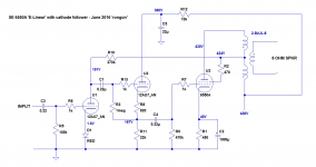
Here's my idea. It may be horrible. I'm not educated in electronics, so I've probably missed some basic, fundamental issues. But I tried my best. What do you think of the attached proposed circuit?
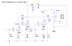
- Single-ended 6550A (or KT88) output tube driving an OPT with 'ultralinear' screen tap.
- 12AX7 input tube with LED bias. The output tube's screen (+435V) feeds the 12AX7 plate through a 270k plate load resistor.
So far, so good. Your typical E-Linear SE circuit. Now here's the part I'm not sure of, and have not seen before:
- Signal from the 12AX7 plate travels to the grid of a 12AU7 cathode follower, which drives the grid of the 6550A output tube. The B+ for the cathode follower is from the main B+ supply, NOT from the screen of the output tube. Since the plate supply for the cathode follower is not coming from the 6550A screen -> 12AX7 plate loop, does that remove the cathode follower B+ from within the feedback loop? To accomplish this successfully, does the 12AU7 CF plate supply need to be regulated?
Go ahead, rip it apart, make me look stupid. I can take it. I'm hoping to learn something from this, and if the consensus is that this circuit might sound pretty good, I have an old push-pull amp chassis that just happens to have all the holes I need already drilled and punched.
Thanks in advance for your input.
--
Here's my idea. It may be horrible. I'm not educated in electronics, so I've probably missed some basic, fundamental issues. But I tried my best. What do you think of the attached proposed circuit?
- Single-ended 6550A (or KT88) output tube driving an OPT with 'ultralinear' screen tap.
- 12AX7 input tube with LED bias. The output tube's screen (+435V) feeds the 12AX7 plate through a 270k plate load resistor.
So far, so good. Your typical E-Linear SE circuit. Now here's the part I'm not sure of, and have not seen before:
- Signal from the 12AX7 plate travels to the grid of a 12AU7 cathode follower, which drives the grid of the 6550A output tube. The B+ for the cathode follower is from the main B+ supply, NOT from the screen of the output tube. Since the plate supply for the cathode follower is not coming from the 6550A screen -> 12AX7 plate loop, does that remove the cathode follower B+ from within the feedback loop? To accomplish this successfully, does the 12AU7 CF plate supply need to be regulated?
Go ahead, rip it apart, make me look stupid. I can take it. I'm hoping to learn something from this, and if the consensus is that this circuit might sound pretty good, I have an old push-pull amp chassis that just happens to have all the holes I need already drilled and punched.
Thanks in advance for your input.
--
Attachments
Last edited:
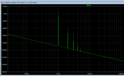
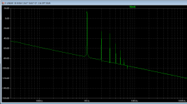
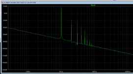
For whatever it's worth, here are some screen grabs from LTspice, showing the FFT's at 1W out, 5W out, and 10W out.
Even at 10W out into 8 ohms, the amp's not clipping.
LTspice says THD would be about 0.4% at 1W out, 2% at 10W out. That seems too good to be true for a single-ended tube amp. I must have done something wrong...
--
Even at 10W out into 8 ohms, the amp's not clipping.
LTspice says THD would be about 0.4% at 1W out, 2% at 10W out. That seems too good to be true for a single-ended tube amp. I must have done something wrong...
--
Attachments
The 12AU7 CF will not have difficulties to fully drive the output stage.
No need to change any thing.
My two pence :
- Since the input impedance of the CF is very high, C1 looks 10 fold too large.
- With a little help of some negative supply, C2 could be removed as long as the cathode bias and its by pass cap.
And so you can "accidently" push the final in A2 (grid current on a strong hit) without disturbing its bias.
Yves.
No need to change any thing.
My two pence :
- Since the input impedance of the CF is very high, C1 looks 10 fold too large.
- With a little help of some negative supply, C2 could be removed as long as the cathode bias and its
by pass cap. And so you can "accidently" push the final in A2 (grid current on a strong hit) without disturbing its bias.
Yves.
I agree that it seems like a good circuit. I'm not sure going to fixed bias is going to do anything good except up the power. That definitely is good. But you will be exchanging bias voltage "riding" in self bias for blocking distortion in fixed bias when either one is overdriven. That seems like a wash.
One thing for certain: As it is now c2 at 1000uf is too big. It just exacerbates that bias change "riding" effect. You want it to self adjust faster by using a bypass cap no more than half or a third the size of c2 as it is drawn.
Edit: "That seems like a wash". Unless you go to direct coupling between the CF and the output tube.
Last edited:
LTspice says THD would be about 0.4% at 1W out, 2% at 10W out. That seems too good to be true for a single-ended tube amp. I must have done something wrong...
Build 'er up and take some distortion measurements.
jeff
Yvesm said:- Since the input impedance of the CF is very high, C1 looks 10 fold too large.
Thanks, nice catch. I dropped the value of C1 down to 10nF and output response didn't change. Much easier to find a really nice 0.01uF cap than it is to find an equal quality 0.22uF one.
I agree that it seems like a good circuit. I'm not sure going to fixed bias is going to do anything good except up the power. That definitely is good. But you will be exchanging bias voltage "riding" in self bias for blocking distortion in fixed bias when either one is overdriven. That seems like a wash.
One thing for certain: As it is now c2 at 1000uf is too big. It just exacerbates that bias change "riding" effect. You want it to self adjust faster by using a bypass cap no more than half or a third the size of c2 as it is drawn.
The problem with a C2 that is of a smaller value is that it will cause a resonance inside the feedback loop that will give a bump in response at about 10Hz. This is something the OPT can't handle, so will cause early saturation at higher powers.
I do agree that a 1000uF cap is just too damned big. But I'm not sure what effect reducing C2 to 330uF would have on the overall circuit, including the feedback loop.
Anyway, I'm happy the circuit looks basically sound. I was worried about what effect the cathode follower would have on the E-linear feedback loop from the OPT screen tap to the plate of the 12AX7. It looks like it's generally a good idea to have the cathode follower in there, because it makes it possible to use a 12AX7 in the input stage.
Re: trade-offs between fixed bias and cathode bias --
I think the 'ultimate' solution would be to have the cathode load resistor of the CF going to a negative DC supply, so that the cathode of the CF would be at -40V or so, and would provide both the signal input and the grid bias for the output tube, but with the possibility of DC coupling the CF cathode to the output tube grid. That would be ideal except for the added complication of a regulated negative voltage supply to feed the cathode follower 'tail.' Any grid current drawn from the output tube would add to the load on that negative supply, causing it to 'sag.' If that happens, then the grid bias on the output tube would go more positive, causing it to draw more current, and away we go into runaway. That seems too complicated a solution at this point, especially with my ham-fisted building skills.
If nobody sees any serious mistakes, then it looks like I have a simple enough project that I might actually be able to pull off successfully!
--
Last edited:
One thing for certain: As it is now c2 at 1000uf is too big. It just exacerbates that bias change "riding" effect. You want it to self adjust faster by using a bypass cap no more than half or a third the size of c2 as it is drawn.
OK, so if I reduce the value of C4 to only 0.01uF, and reduce the value of C2 to 47uF, I get a +1dB bump at about 20Hz, with a smooth rolloff below that. Since I have a few 47uF 160V metallized polyester film caps, maybe I'll try those for C2 and live with the small bump in response. It might actually sound nice.
So in the end, yes, a much smaller value cap will work there, which should avoid the worst bias change effects.
I also tried DC-coupling the 12AX7 to the 12AU7, and that seems to have worked with no ill effects at all.
--
Well, well.
So, a "no link, no bypass caps" amplifier is feasible")
Indeed they are more or less moved in the PSUs
Oh, forgotten :
Consider using shunt regulated negative supply, so it will be able to absorb an eventual grid current.
A single zener can do the job.
Yves.
So, a "no link, no bypass caps" amplifier is feasible
Indeed they are more or less moved in the PSUs
Oh, forgotten :
Consider using shunt regulated negative supply, so it will be able to absorb an eventual grid current.
A single zener can do the job.
Yves.
Last edited:
Thanks Yves.
I don't think a +450V 200mA regulated PSU is forthcoming. That would be a beast.
The power supply reservoir cap and filtering cap are unavoidable. Still, if I make the positive power supplies dual mono, I can make them CLC type with reasonably small value electrolytic capacitors. Perhaps 47uF 500V will do.
If I try to DC-couple the cathode follower to the output tube grid, that means the negative supplies will pass the current draw from the cathode followers. Since I have about 7.5mA going through each 12AU7, that means a -220V 15mA supply needs to be constructed. Which single zener can provide that? It will have to be a string made of lower voltage zeners. I think a string of nine 25.2V zeners should provide the -225V I need.
Of course, I could use a DN2535 MOSFET as a current sink for the 12AU7 cathode follower's load. Then I'd only need a -100V 15mA supply or thereabouts, in which case a string of four 25V zeners should suffice (each one dissipating 375mW).
But this is getting complicated. I need to build something simple to get my confidence up, after a couple of projects in a row that were abject failures. I think I can pull off the simple version of this design, with the DC-coupled voltage amp to CF, and a small value cap bypassing the output tube cathode resistor.
--
Well, well.
So, a "no link, no bypass caps" amplifier is feasible
Indeed they are more or less moved in the PSUs
I don't think a +450V 200mA regulated PSU is forthcoming. That would be a beast.
The power supply reservoir cap and filtering cap are unavoidable. Still, if I make the positive power supplies dual mono, I can make them CLC type with reasonably small value electrolytic capacitors. Perhaps 47uF 500V will do.
Oh, forgotten :
Consider using shunt regulated negative supply, so it will be able to absorb an eventual grid current.
A single zener can do the job.
If I try to DC-couple the cathode follower to the output tube grid, that means the negative supplies will pass the current draw from the cathode followers. Since I have about 7.5mA going through each 12AU7, that means a -220V 15mA supply needs to be constructed. Which single zener can provide that? It will have to be a string made of lower voltage zeners. I think a string of nine 25.2V zeners should provide the -225V I need.
Of course, I could use a DN2535 MOSFET as a current sink for the 12AU7 cathode follower's load. Then I'd only need a -100V 15mA supply or thereabouts, in which case a string of four 25V zeners should suffice (each one dissipating 375mW).
But this is getting complicated. I need to build something simple to get my confidence up, after a couple of projects in a row that were abject failures. I think I can pull off the simple version of this design, with the DC-coupled voltage amp to CF, and a small value cap bypassing the output tube cathode resistor.
--
- Status
- This old topic is closed. If you want to reopen this topic, contact a moderator using the "Report Post" button.
- Home
- Amplifiers
- Tubes / Valves
- I had an idea for a SE UL amp with local feedback output stage