Hello all.
I have a pair of 55e .They came to me with u/s written on side so could have fault.
I have tried them out an both output sound ok but the large reisistor R32 gets hot.
It got to 95c in about 2 mins so I shut it off.
I wasn't sure if the way I connected the speaker was a cause.
I just connected it across pins 1 and 2.
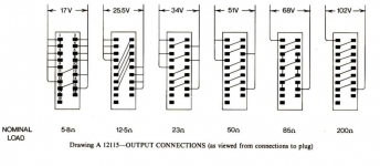
Do I need to connect it like the diagram?
thanks
I have a pair of 55e .They came to me with u/s written on side so could have fault.
I have tried them out an both output sound ok but the large reisistor R32 gets hot.
It got to 95c in about 2 mins so I shut it off.
I wasn't sure if the way I connected the speaker was a cause.
I just connected it across pins 1 and 2.
Do I need to connect it like the diagram?
thanks
Attachments

I de soldered it .
I have just connected in reverse bias with 12v through a 1.5k resistor and metered across it and it read 5.35v so It think its ok '
it also passed the dioded tst on my dvm ok
I have just connected in reverse bias with 12v through a 1.5k resistor and metered across it and it read 5.35v so It think its ok '
it also passed the dioded tst on my dvm ok
There is an awful amount of voltage to drop across the 180R so maybe it is alright if the HT is correct at 28 Volts.
Thanks Jon.
I have made up the proper wiring connection now and it is still hot.
The basic schematic says ht is 38v volts and I am getting 39 so thats ok.
Mr5 is working and measures 5.7 with respect to ground so its ok too .
When I powered it up for the first time I smelt that burning smell and that is how I discovered.
R32 hot.
The smell probably was just dust build up, I smell that smell when testing heaters that haven't been used for time regularly at work.diyaudio
I don't know what power rating the resistor is as my schematic does not show it, so I cant find out its max working temp.
The amp sounds ok so it could be normal
thanks
I have been searching more and r32 is a an 8w ceramic 5% resistor,still not sure of its working temp though.
Hello all.
I played chicken with it and let it run to see what it would max out at over 10 min.
R32 stabled out at about 175celcuis and mr5 at 80c.
It still sound ok though
I played chicken with it and let it run to see what it would max out at over 10 min.
R32 stabled out at about 175celcuis and mr5 at 80c.
It still sound ok though
Hello all.
I have done a lot more research and so far I have set the bias and set the Emitter voltage of Tr3 to 5.5 volts.
I have also checked all the transistors with dvm and all were ok.
I have just ordered new nichicon caps for it
I put some better speakers on it and it does have a good sound
I have done a lot more research and so far I have set the bias and set the Emitter voltage of Tr3 to 5.5 volts.
I have also checked all the transistors with dvm and all were ok.
I have just ordered new nichicon caps for it
I put some better speakers on it and it does have a good sound
If the outside is at 175°C, then what is the temperature of the resistive element?.................R32 stabled out at about 175celcuis and mr5 at 80c............
What is the resistance at that unknown temperature?
What is the reliability at that temperature?
Andrew is challenging your perception of what the temperature of the resistance wire buried in the cement encapsulation really is (an occupational hazard, I understand). These are rhetorical questions that you can't answer by simple measurement or prediction unless you have precise construction detail for such obsolete products. Still, the concern is relevant to whether the resistor is working within original spec. and safe enough - or not.
FWIW, 175C is stinking hot and skin-sticking dangerous. It would need to be a long way from plastics, paint PCBs etc. of normal types to be called safe in any consumer device. I imagine that as broadcast monitors, these products would have been tendered in the face of stiff competition and such corner-cutting would be routine. Fit a 20W WW resistor if it will fit.
FWIW, 175C is stinking hot and skin-sticking dangerous. It would need to be a long way from plastics, paint PCBs etc. of normal types to be called safe in any consumer device. I imagine that as broadcast monitors, these products would have been tendered in the face of stiff competition and such corner-cutting would be routine. Fit a 20W WW resistor if it will fit.
Thanks fr that.
I didn't understand what andrewt said.
On the schematic the resistor goes through the diode and only 2 transistors are powder by the 5.6v generated by diode.
The transistors all meter out ok and funtion so I am lead to think that its not a fault condition .
The resistor meters out ok too.
I think your idea of a 20w one is a great idea
Thanks for the help all

Yes, as far as the amplifier is concerned, though zener MR5 conducts the majority of current to reduce the supply voltage from 38V (I read a silly 88V on the schematic diagram) to 5.6V. That's more than 5W dissipation in R32 and it would be approaching its max. rated continuous working temperature, as you probably realize.
In other words, R32 would still get hot if not hotter, should TR6,7 driver transistors be open circuit or removed.
In other words, R32 would still get hot if not hotter, should TR6,7 driver transistors be open circuit or removed.
The original R32 is a 8w welwyn f77 resistor.
It would seem that its normal by design to get hot, although i am searching for a supplier of a 15-20w replacement.
Both tr6,7 meter out and they are driving the output tr ok and it does sound good.
Thanks Ian you have been helpful
I have just double checked the output tr in case one was down.
So everything that runs of the r32 is ok
Last edited:
You may find that new parts stocked anywhere of this rating, have changed over the years. Larger power resistors are now small and rely on heatsinks to achieve their ratings. Small heatsinks are indicated and Quad's main sink is likely too far to run leads. Still, these are cute and compact: AP821 180R J 100PPM | Arcol AP821 Series TO-220 Radial Thick Film Resistor 180Ω 5% 20W 100ppm/C | Arcol
Here are more common metal clad types, probably Chinese origin and resold by many distributors:
THS25180RJ TE Connectivity / CGS | Mouser
It could be difficult to fit these where needed. For the safety benefit, consider this for a future project when you were convinced everything works satisfactorily, electrolytic capacitors are in good shape (doubtful) and you are happy to keep them. Meantime, take care 😉
Thanks Ian
You have been helpful.
I have new ceramic 15w on there way
i also have ordered new caps throughout .
I have also rewired it to 8ohm and replaced the plessey connectors with gold banana plugs and phono's
You have been helpful.
I have new ceramic 15w on there way
i also have ordered new caps throughout .
I have also rewired it to 8ohm and replaced the plessey connectors with gold banana plugs and phono's
The matters for resistor temperature are surface area and air flow, regardless of power rating. So if the replacement is not much larger, nor fitted with a heatsink, you'll still have a hot resistor to cope with.
The exercise probably won't hurt if the resistor fits similarly and isn't prone to personal contact anyway. You were fortunate to find 180R ceramic resistors above 5W rating though. Good luck with the recap too 🙂
The exercise probably won't hurt if the resistor fits similarly and isn't prone to personal contact anyway. You were fortunate to find 180R ceramic resistors above 5W rating though. Good luck with the recap too 🙂
Maybe just modify the circuit. remove R32 and MR5, and install an extra circuit for 5.6v supply. In my opinion, get a +10v from the coil which the -10v come from, then use a 7805 and 1n4148 to get 5.6V instead. will reduce heat. I don't know why Quad engineer designed it like this, danger and a waste of energy, can anyone explain?
- Home
- Amplifiers
- Solid State
- QUAD 50e speaker wiring