I have recently been bitten by the tube bug and now have a couple of EL84 PP amps to restore. First up is an early Stereo 20 with 3921 OPTs - Date stamped on underside is March 25 1959.
I have what is apparently the correct circuit diagram for the early version and want to go through the restoration keeping close to the original but am open to make some small component "upgrades" if some small improvements can be had.
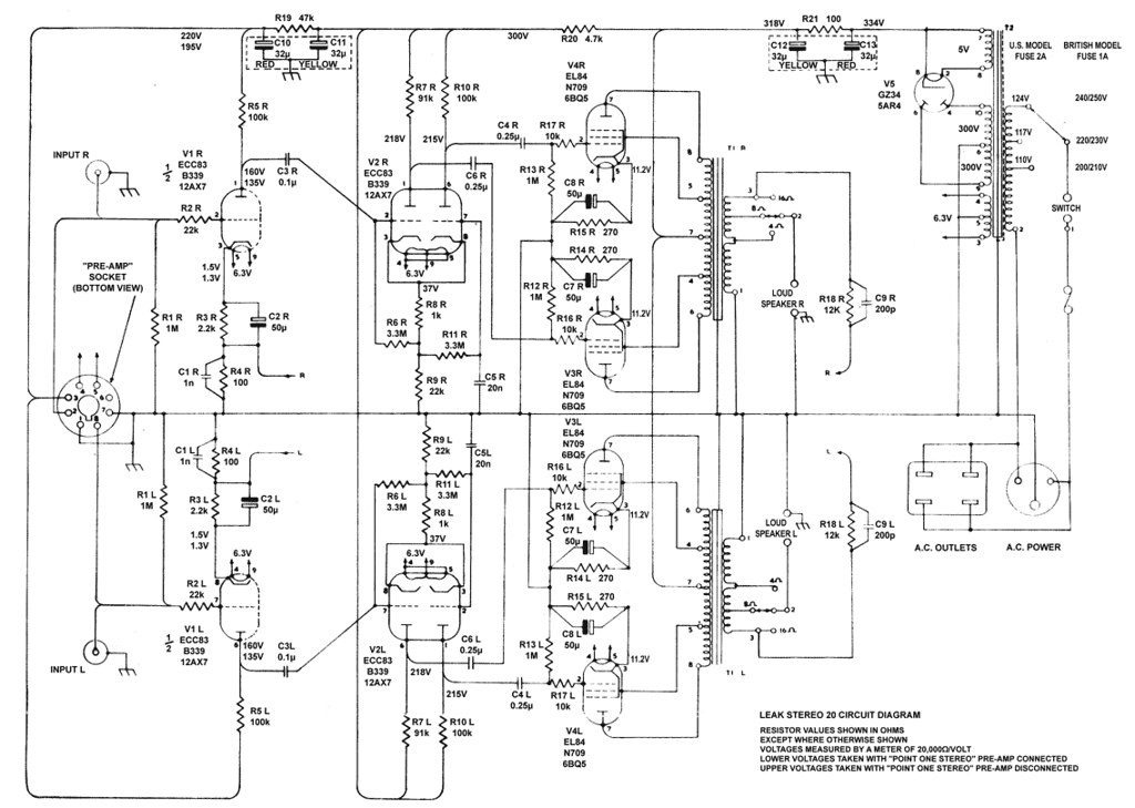 Leak Stereo 20 3921 OPT by Bregtje Cals, on Flickr
I plan to try 5751 tubes in place of ECC83s and probably a passive pre like the Luminous Audio Axiom or possibly make my own with an Alps pot etc.
My main question is whether it is worth fitting a power supply choke in place of the 100R resistor in the Stereo 20? Apparently there are benefits to be had from using something like this: 157Q Hammond Manufacturing | Mouser
I have what is apparently the correct circuit diagram for the early version and want to go through the restoration keeping close to the original but am open to make some small component "upgrades" if some small improvements can be had.
Leak Stereo 20 3921 OPT by Bregtje Cals, on FlickrI plan to try 5751 tubes in place of ECC83s and probably a passive pre like the Luminous Audio Axiom or possibly make my own with an Alps pot etc.
My main question is whether it is worth fitting a power supply choke in place of the 100R resistor in the Stereo 20? Apparently there are benefits to be had from using something like this: 157Q Hammond Manufacturing | Mouser
All electrolytic caps. should be replaced, as they literally dry out over time.
A mix of 716P series "Orange Drop" film and Soviet surplus K40 paper in oil (PIO) parts will deal of any signal caps. that are electrically leaking.
Check carbon composition resistors for drift and noise. Replace failed parts with carbon film parts, except in grid stopper positions, which remain carbon composition.
Replace wirewound resistors only if physical deterioration is observed.
Sourcing a totally satisfactory replacement 5AR4/GZ34 rectifier can be problematic. If you employ the uploaded series SS diode tweak, a reasonably priced Sovtek 5AR4 will be just fine. My anal nature says use UF4007s, instead of the 1N4007s shown.
The OEM PSU filter is CRC. If you can source a 250 mA. rated choke of about 2 H., whose DCR is <= 100 Ω, filter action can be improved. Replace R21 with the choke and any necessary extra resistance. The 157Q does not have sufficient current handling capability.
Attachments

My main question is whether it is worth fitting a power supply choke in place of the 100R resistor in the Stereo 20? Apparently there are benefits to be had from using something like this: 157Q Hammond Manufacturing | Mouser
The question you should ask youself is this: Can I hear any hum in the speakers with teh power supply as it is?
My guess is you cannot. If you can there is probably one or more lectrolytics faulty. The electros are adequately sized, and teh cuircuit configuration is not particulary power rail ripple sensitive.
If you cannot hear any hum now, why waste money on a choke?
If you can hear just a touch of hum, and no existing parts are faulty, you can fit bigger capacitors in any or all of the C10, C11, or C12 position. But NOT the C13 position. Fitting a bigger electro is possible now, but would not have been readily avaiulable when the amp was new. Fitting a big electro is cheaper than fitting a choke, and while it may not reduce ripple as much, most likely will reduce it enough to make it inaudible.
Don't foget that not all hum that may be audible comes via the HT rail. There may be some coupling via the heater circuit, or a tube amy have excesive heater-cathode leakage.
Check carbon composition resistors for drift and noise. Replace failed parts with carbon film parts, except in grid stopper positions, which remain carbon composition.
Be carefull about replacing carbon composition reistors with carbon film types. Carbon film types of similar physical size have lower voltage ratings, and are inherently less tolerant of over-voltage spikes, such as tube flash-over or slips of a multimeter probe.
With carbon composition, if the power rating is adequate, that's all you have to worry about (apart from using the correct resistance of course).
But with carbon film, which was not routinely used until solid state arrived, you must check that the voltatge rating is adequate, as well as the power rating. For anode and screen resistors, it's best that they be rated to take the full HT voltage. They will give a long stable service life then.
Last edited:
Keit is absolutely correct about making certain that the ratings of parts are more than adequate for the operating conditions they will be subjected to. Long term reliability is quite important.
The advantage of carbon film resistors over carbon composition resistors is less noise and drift.
Grid stopper positions are a special case. Here, suppression of parasitic oscillation is the goal. Being both non-metallic and non-inductive makes carbon comp. parts "best" in the stopper role. Noise is a function of current and current in small signal grid circuits is TINY. Small amounts of value drift are also unimportant, in the stopper role.
Metal film resistors, with their superior noise factors, are excellent in grid to ground positions. OTOH, in plate and cathode circuitry, metal film parts can adversely impact on voicing.
You select parts based on the specific jobs they have to perform. There is no single "best" variety for all situations. Something may work very well in 1 situation and be absolutely dreadful in another.
Thanks gents for your pointers on resistor types and on capacitor replacements! How much would be acceptable to up the capacitance of C10, C11, C12? Andwould C13 overstress the GZ34 if upped to 47uF?
I think I will try the amp out with new caps and resistors and then make a decision whether to try a choke. Seems like a more sensible course to take 🙂
I think I will try the amp out with new caps and resistors and then make a decision whether to try a choke. Seems like a more sensible course to take 🙂
First about the choke, I think you should not replace it (if you do replace, try different value to see any difference) until you check the hum level at R21. A) Left channel 1) at light or no load 2) at full load to check the hum level at the output and B) Repeat same for Right channel and C) repeat for both channel. This is only way to determine if the capacitance or inductance is sufficient. For upped the capacitance you mentioned I think < 30% increased is not critical (watch the voltage rating) as there is no initial surge to worry about, the important thing you have to monitor and record current value first, like check their actual value as well as new components with LCR meter.
Second, since this is a PP amp, the hum would be cancel out mostly at the transformer, so I think the change would affect more on the front end and driver stage than the output state. And if so, consider separate filter for each channel rather than combined filter, the component value can be kept the same value but reduce size and cost.
Second, since this is a PP amp, the hum would be cancel out mostly at the transformer, so I think the change would affect more on the front end and driver stage than the output state. And if so, consider separate filter for each channel rather than combined filter, the component value can be kept the same value but reduce size and cost.
Last edited:
Thanks gents for your pointers on resistor types and on capacitor replacements! How much would be acceptable to up the capacitance of C10, C11, C12? Andwould C13 overstress the GZ34 if upped to 47uF?
I think I will try the amp out with new caps and resistors and then make a decision whether to try a choke. Seems like a more sensible course to take 🙂
C10 and C11 are decoupling parts. As the 12AX7/ECC83 triode runs with a low plate current, leaving the decoupling values unchanged is probably "correct".
The 5AR4/GZ34 data sheet shows the capacitance max. as 60 μF. Therefore, increasing C13 to 47 μF. is quite sensible. C12 is the B+ reservoir and will definitely benefit from an increase in value. I'd entertain as much as 100 μF. of capacitance in the C12 position.
I would NOT increase C13.
While it may be within the rectifier ratings to do so, power rectification was never really something that tubes were suitable for. Oxide coated cathodes don't like the high peak-to-average current ratio that large capacitors cause. It's just that nothing else really good was available until silicon rectifiers became available in the 1960's - whereupon most manufacturers immediately stopped using tube rectifiers.
The rectifier is the most failure prone tube in any tube equipment. It's ratings are a compromise between cost and durability. If you increase the filter input capacitor size up to the rating, the tube may fail more often.
Last edited:
Hi afroaudio,
What they are talking about is the hot switching current. This is a balance between efficiency and tube life, especially when you begin to approach boundaries. Given the low benefit from increasing that first capacitors size, I wouldn't. Even if you have to replace it.
I have my own Leak 20 to restore at some point. That first cap will stay the same value. The second capacitor will be increased a little, but with the amplifiers I have done so far there hasn't been anything in the way of improvements when playing music.
Hi Eli,
I would back you on most things, except in this area. Call it a judgement call. Mine is more conservative.
-Chris
Hi Eli,
I would back you on most things, except in this area. Call it a judgement call. Mine is more conservative.
-Chris
You have to be comfortable and there's nothing wrong with "belt and suspenders".
Install the series SS diode tweak to stop power on arcing of current production 5AR4s. Add a CL-130 inrush current limiting thermistor in the line between rectifier cathode and PSU filter. Now, you can safely take that 1st filter cap. up to 100 μF. 😀 Of course, the reservoir position gets upgraded too. 😉
FWIW, my preference is plenty of energy storage. It's needed, when bass heavy passages are played.
Hi Eli,
The series rectifiers aren't something I normally use, but then I'm not pushing anything. Interesting use of the CL-130 - I have some. But, the reservoir position is the only one I have increased capacitance. The series resistor or choke protects the rectifier nicely. The more effective that is, the less effective increasing the first capacitance will be.
Now you have me thinking about your surge resistor. I like using a relay and resistor to do actual AC inrush limiting. Would the little 6BQ5 stereo draw enough B+ to allow the CL-130 to act in a meaningful way located in the HT line? My guess is that 6L6GC class amps would.
I have a Heathkit set of iron from a 6BQ5 type stereo that I'll do a new build with. I can try your trick out with that. One thing I like to do is install an MOV directly across the primary of the power transformer. This prevents the turn-off arc in the power switch that sometimes happens. I noticed that power switches really last a lot longer if you do this. That, and it better protects your electronics in the event of a real AC power surge.
-Chris
When tube rectifiers were phased out in favour of silicaon rectifers in tube-based TV sets, the use of a thermistor to limit power-on inrush was quite common.
Hi Keit,
Yes, they were. I had not seen them used in the HT line. I'll bet they couldn't have been safety certified with a part that heats up in a 300 + VDC power supply. Insulation would have been an issue.
I was servicing in Canada and saw both tube and solid state rectifier circuits. But I didn't service TVs and was happy not to. They are dust magnets, filthy inside.
-Chris
I managed to get a job with a TV & stereo repair place when I was still at school.
You are certainly right about tube TV's being dust magnets. I used to use a vacuum cleaner to clean them out before working on them. Unfortunately that would occaisonally cause another fault. Tube stereos were usually very clean.
They were safe enough though. The thermistor was mounted well clear of anything else, and in a place where dust didn't build up.
TV set safety back then was a bit like car safety back then. Not obvious. Manufacturers learnt how to do simple low cost or cost free things that improved safety and reliability - but they were often things that those not in the industry were not aware of.
A good analogy was the infamous Ford Pinto compact car in the US. Early production Pintos tended to burst into flame if rear-ended. Ford moved the fuel tank forward 50 mm or so and thereby eliminated the problem. If you looked at a late production Pinto you wouldn't know what was different or how it mattered.
Car now have all manner of obvious safey features - crash bars in the doors, airbags, smart brakes, etc etc. But the darn things catch fire now. Just what you want when you'sve just had an accident and are sitting there stunned and the door is jammed. Apart from Pintos and the occaisonal British vehicle, you hardly ever heard of cars catching fire in the '50's and '60's. It was very rare.
Same with TV sets. Subtle measures were taken in circuit layout to prevent cascading fault conditions leading to fire.
FWIW, I learned about NTC thermistors in B+ circuitry from Jim McShane, AKA "Mr. Citation". Inrush limiting can't go on the power trafo primary, as it will adversely slow bias supply rise down. So, depending on what you have to accomplish, you can put the thermistors in a number of places.
The series SS diode tweak is not original with me. As it has clear benefits in stopping "fireworks'' in JJ and Sovtek 5AR4s, I've added it to my bag of tricks. A claim has been made that the tweak will slightly increase the service lives of well used OS rectifiers. I can't comment, up or down, on that claim.
The cold resistance of a CL-130 is 50 Ω. That resistance will provide protection at power on. I agree with the assessment that a 6BQ5/EL84 amp will not draw enough current to achieve full heating/resistance reduction. I don't think that is a problem.
A larger 1st capacitance in a П section PSU filter should improve regulation. It always comes down to try the ideas on the bench and see what happens.
Hi Eli,
Fair enough. I will give the CL-130 a whirl in my next build. I think you are onto something there, many thanks.
The larger 1st capacitor will definitely make for better regulation, no question! I'm trading this off against hot switching current. Resistance in this position will undo some of the gains in supply voltage regulation - but you are more than aware of that.
The SS diodes won't hurt anything, so they are like insurance really. I'm thinking on this, and if I do increase capacitance values the scales will tip to the "needed" column.
The line thermistors are original equipment on many amplifiers, which I see cycling with power draw. That's why I would use a resistor that is switched out after voltage builds up a little. The B+ would be delayed as well. Bias before B+ every time.
Hi Keit,
I owned a Pinto once. It got rear ended and didn't burn (I was gone, it was out of gas). They used to drop the tank on the road when hit. My poor little Pinto looked like a boomerang after it was struck. No warranty on that abuse.
-Chris
The line thermistors are original equipment on many amplifiers, which I see cycling with power draw.
They were not all that common in hi-fi amplifiers, never used in PA, but very common in TV sets.
I think the cycling is why. A tube-based TV set's draw is pretty constant - much of it going in deflection. It may increase if you tune to an unused channel.
Where the amplifier is a Class A/Class AB1 not driven hard, there will not be a problem.
Hi Keit,
Well, I serviced mostly amplifiers, Home and PA. Some MI back then. Later on the tube work became almost exclusively home audio and Fender amps. Those inrush current resistors would make more sense in a TV, but I wasn't the one servicing those. A fair number of audio amplifiers here used inrush current limiters. Eico liked using a cement resistor attached to a bi-metalic strip with contacts on it to short the resistor. It cycled which is why I changed mine to a relay that closed when the voltages got high enough and stayed closed. The cycling was noticeable, maybe because I knew it was there.
Inrush current surge resistors wouldn't be much use in PA amps used in paging as those are left on all the time. I saw them in audio amplifiers, but certainly not all of them.
-Chris
I serviced a limitted number of PA amps, and guitar amps as well. Never saw thermistors in any of them, as I recall.
Unlike hif-fi amps, which were Class AB1 and thus the HT current varied nor more than 10 to 15% from idle to full drive, these PA & guitar amps were Class B, where the HT current is almost directly proportional to drive.
So thermistor inrush limitting should be fine in a hi-fi amp, but not in a PA or guitar amp (SE practice or busking amps excepted) due thermistor temperature cycling. It's not just a matter of upsetting operating conditions, continually temperature cycling would induce coffin-manson failure of the thermistor. You are right that inrush limitting would be less important in a PA amp left on all the time.
The thermistors probably could not take the shock and vibration that a guitar amp encounters anyway.
- Status
- Not open for further replies.
- Home
- Amplifiers
- Tubes / Valves
- Leak Stereo 20 Power Supply Choke?