Did some measurements on some parts express inductors I had. Thought the information might be of some interest to others. I used a .3mH #20awg coil, a .25 mH #18awg, and a .2 mH #18awg.
I use the Ls/Rs model for an inductor. I ran the 3 pieces I had from 20 hz out to 100 Khz.
I also compared the inductors free air and lying on a 2 sided clad pc board.
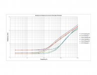
First, the inductance. Note that all are flat to 500 hz. The units lying on the copper started reducing inductance noticeably at 1Khz, this is a consequence of the copper conductivity trying to prevent the field from penetrating the pc board. The stopping of the penetration by a conductive surface of permeability 1 will always lower the inductance. Steel of course, would increase the inductance.
Note that even the air coils exhibit inductance drop. That is a consequence of the proximity effect on the current path within the wires. The proximity effect is changing the apparent diameter of the coils. If you find an online coil inductance calculator, try changing the diameter in small increments. Smaller diameters produce lower inductances. This indicates that the current is moving to the inside edge of the copper wires.
Next, resistance (I used a log vertical scale for ease of seeing). All three coils in air extend out to 2khz before the wire resistance starts to rise. Both 18 guage coils have doubled their series resistance by 5 Khz, the 20 guage doubles by 9 Khz.
Notice what happens as a result of the copper clad board proximity. The series resistance increases an order of magnitude by 6 Khz for the two 18 guage coils (about 2 ohms), and the 20 guage does it above 10Khz but below 11.
This is a light copper clad, btw, not very thick.
I expect this to be much worse for a #10 or #12 solid, I'm winding a 10 guage coil with instrumentation wires to detail exactly what the proximity effect will do to the resistance.
jn
I use the Ls/Rs model for an inductor. I ran the 3 pieces I had from 20 hz out to 100 Khz.
I also compared the inductors free air and lying on a 2 sided clad pc board.
First, the inductance. Note that all are flat to 500 hz. The units lying on the copper started reducing inductance noticeably at 1Khz, this is a consequence of the copper conductivity trying to prevent the field from penetrating the pc board. The stopping of the penetration by a conductive surface of permeability 1 will always lower the inductance. Steel of course, would increase the inductance.
Note that even the air coils exhibit inductance drop. That is a consequence of the proximity effect on the current path within the wires. The proximity effect is changing the apparent diameter of the coils. If you find an online coil inductance calculator, try changing the diameter in small increments. Smaller diameters produce lower inductances. This indicates that the current is moving to the inside edge of the copper wires.
Next, resistance (I used a log vertical scale for ease of seeing). All three coils in air extend out to 2khz before the wire resistance starts to rise. Both 18 guage coils have doubled their series resistance by 5 Khz, the 20 guage doubles by 9 Khz.
Notice what happens as a result of the copper clad board proximity. The series resistance increases an order of magnitude by 6 Khz for the two 18 guage coils (about 2 ohms), and the 20 guage does it above 10Khz but below 11.
This is a light copper clad, btw, not very thick.
I expect this to be much worse for a #10 or #12 solid, I'm winding a 10 guage coil with instrumentation wires to detail exactly what the proximity effect will do to the resistance.
jn
Attachments

Last edited:
Nah. I was thinking of using them at work instead...😉Are you going to use those inductors in your new project?
When measuring the inductance, my machine is only capable of providing the L and R component values, not what causes the values.. As such, when considering the results, it is important to understand what each is comprised of.
For L, there is the energy stored in the base field as well as energy stored in external devices. For R, there is the dissipation which occurs in the wire itself, and the dissipation externally due to eddies.
For air coils with no external conductive materials nearby, all the Rs is within the wire, and it increases entirely due to proximity effect in the wire forcing the current to take increasingly smaller fractions of the wire area.
When the clad was next to the coil, the machine is interpreting the losses in the clad as additional series resistance, even though the effective resistance is not the coil wire, but the external losses in the copper clad.
If the crossover needs accuracy, putting the coil against a copper pad will increase the series resistance of the coil quite a bit. These kinds of measurements can give one information for determining the extent of the changes in resultant circuit operation.
jn
Last edited:
- Status
- Not open for further replies.