Thanks for the reply.
So far testing has been using a mediocre bench power supply - sounds like I should eliminate that first. My next step was going to test the oscillator on some batteries, longer term I have some super regulators (Peranders' SSR01/2).
When oscillating correctly, what does the output look like on a scope? Do you see HF/VHF parasitic oscillations?
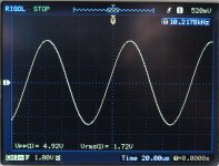
I get nice sine wave, however, if I scroll down to nS region, I was able to observe some HF oscillation as well. I am not sure where it came from. My scope BW is over 230MHz, it's possible the scope is picking up something else. Anyway, you have to adjust the final sine wave on spectrum analyser or good quality sound card, that's what you are after.
Attachments
I would recomend a battery powersupply after many testsetups with ordinary supplys.
Sometimes it was not a problem to use the ordinary Hameg supply, sometimes "strange things happend" . I aggree that it is not so preatty as normal powersupply but much easier to handle.
Otherwise you change the setup and got new problems with a bad THD, because an "new" influence on the Osz. Even the GND cable was able to catch up oszillations, and a setup earthed is not always the best choice.
I just tried with peranders' SSR01/02, and still had a problems - though I have to admit to not spending too much time trying to get it to oscillate nicely. I find I can easily get one of three modes: no oscillation; saturation; or 19v P2P sine wave (no obvious saturation) but lots of nasty HF noise and instability. I have some PP3s, will give them a crack next! Thanks.
Last edited:
Is your oscillator in the box? Maybe you should post some pictures. BTW, I also have two SSR01 I can use, one is populated and the other one is just a PCB I didn't finish yet. But I had no need to use them since I have good results with Frex' zenner regulator, which I measured and gives around 4-6uV if I remember correctly.
Last edited:
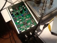
Will send some pictures when I get a chance. The oscillator is not really in the box, I have it slotted into the recommended enclosure, but no end plates or lid. Some PP3 battery clips are on their way, will hook them up and drill the end plates. Did you drill holes in the lid so you can adjust whilst fully enclosed - that seems like a good option. Thanks.
No , I didn't drill any holes in the lid, I was lazy to do that. I don't think is necessary, unless you want the convenience of amplitude adjustment.Will send some pictures when I get a chance. The oscillator is not really in the box, I have it slotted into the recommended enclosure, but no end plates or lid. Some PP3 battery clips are on their way, will hook them up and drill the end plates. Did you drill holes in the lid so you can adjust whilst fully enclosed - that seems like a good option. Thanks.
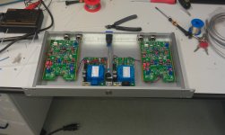
What are those PSUs? Any schematics?Just a post for those ones, who like pic's.
And for me who like to show what he has builded up
I had a little more luck this evening, managing to get the oscillator to work pretty well, though not reliably.
Rather than solely using the high impedance scope input, I added a 100k load. This seemed to calm things down and, with careful adjustment of the gain and amplitude controls, I was able to get a respectable 10kHz sine wave; clean, 5V pp, reasonable THD.
However, if I cycled the power with the gain control anywhere near the required level to start oscillation, I would have a 1MHz parasitic on top of the 10KHz wave. This could only be avoided by powering the oscillator with the gain control set materially less (multiple turns) than the level required to start oscillation. The higher the amplitude setting, the harder it was to start the oscillator without the 1MHz signal.
In summary, the only time I've had reasonable success is: 100k load; amplitude set to mid; gain turned down; slowly increase gain until oscillation, and once stable; increase amplitude to 5v pp. This would work fine, but power cycle would result in 1MHz parasitic and you would have to turn off and repeat this whole process.
This is still half in the case and using SSR01/2 regulators.
Nice build, btw!
I had a little more luck this evening, managing to get the oscillator to work pretty well, though not reliably.
Rather than solely using the high impedance scope input, I added a 100k load. This seemed to calm things down and, with careful adjustment of the gain and amplitude controls, I was able to get a respectable 10kHz sine wave; clean, 5V pp, reasonable THD.
However, if I cycled the power with the gain control anywhere near the required level to start oscillation, I would have a 1MHz parasitic on top of the 10KHz wave. This could only be avoided by powering the oscillator with the gain control set materially less (multiple turns) than the level required to start oscillation. The higher the amplitude setting, the harder it was to start the oscillator without the 1MHz signal.
In summary, the only time I've had reasonable success is: 100k load; amplitude set to mid; gain turned down; slowly increase gain until oscillation, and once stable; increase amplitude to 5v pp. This would work fine, but power cycle would result in 1MHz parasitic and you would have to turn off and repeat this whole process.
This is still half in the case and using SSR01/2 regulators.
Nice build, btw!
I just got mine finished, up and running. I found that the gain control only needed to be about +1/2 turn cw, maybe 3/4 for it to run consistently. The amplitude is at +6 cw and 1.5Vrms output. The 2nd harmonic trim is centered. I didn't find an easy way to measure the trimmers as the voltage in the psu caps throws the measurements off and they don't seem to bleed down. I had to turn the trimmers all the way until I heard their clutch click, then 12.5 turns to get them centered. I'm using a lab bench supply- and old HP 6205B and the onboard cap multiplyer. I presume that if you are using ssr1/2 regulators you are bypassing the cap multiplyer. I seem to recall reading that the Jung style regulators don't like bypass caps.
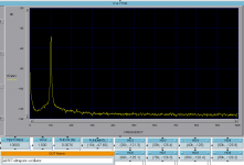
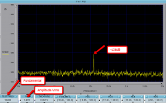
I was able to measure -126db 2nd Harmonic with Vout = 1.5Vrms. Pretty darn good. Didn't have much luck adjusting the 2nd H trim. Used Dick's Twin-T to null the fundamental to -47db.
Ken
Attachments
Frex,
Thank you so much the oscillator works great. It took a few hours to get the hang of tuning it, but, now it works quite consistently.
I have a question for you. I'm getting a frequency of 10,040 hz and would like it closer to 10,000 hz. Your note says adjust R59 and R60 to get closer to 10k. Should I use larger or smaller values? Is there some ratio in need to adhere to?
Thanks again.
Ken
zoom in of the 2nd H attached
Attachments
Sorry for my late answer Coretti.
The Powersupplys are from Funk Audio Berlin. They are quite sophisticaded and are "priceworthy" (around 80€). Mr. Funk is a very nice little bit nerdish engenier for special studio applications. I met him a few weeks ago in his outstanding laboratory and it was a nice talk.
Here are the measurements of those powersupplys:
http://www.funk-tonstudiotechnik.de/PWS-04a_V2-1-Messschriebe-2012.pdf
You must keep in mind, that they are "lowdrop" and do not dissapate a lot of heat.
He has also even better switched Powersupplys in his programm:
http://www.funk-tonstudiotechnik.de/SMPS-14T-Info-2-spaltig.pdf
For me there was no chance to build up my own regulators with the same money/time investment.
Last edited:
I just got mine finished, up and running. I found that the gain control only needed to be about +1/2 turn cw, maybe 3/4 for it to run consistently. The amplitude is at +6 cw and 1.5Vrms output. The 2nd harmonic trim is centered. I didn't find an easy way to measure the trimmers as the voltage in the psu caps throws the measurements off and they don't seem to bleed down. I had to turn the trimmers all the way until I heard their clutch click, then 12.5 turns to get them centered. I'm using a lab bench supply- and old HP 6205B and the onboard cap multiplyer. I presume that if you are using ssr1/2 regulators you are bypassing the cap multiplyer. I seem to recall reading that the Jung style regulators don't like bypass caps.
I was able to measure -126db 2nd Harmonic with Vout = 1.5Vrms. Pretty darn good. Didn't have much luck adjusting the 2nd H trim. Used Dick's Twin-T to null the fundamental to -47db.
Ken
What did you use to measure THD? Is this 0.0076% THD the best your oscillator can do, or is it the limit of measurement method?
I have got much better THD than yours.
What did you use to measure THD? Is this 0.0076% THD the best your oscillator can do, or is it the limit of measurement method?
I have got much better THD than yours.
That result is from my HP8903a. It's the best the 8903 can do, not the oscillator. To get the actual distortion, I would need to calculate it from the measured harmonics, of which only the 2nd is visible. Even the 2nd might be an artifact from the active twin-t filter I used to null the fundamental.
What did you use to measure THD? Is this 0.0076% THD the best your oscillator can do, or is it the limit of measurement method?
I have got much better THD than yours.
I agree.... for a few pp-billion, it must be a lot better. What thd numbers did you get and what did you use to measure it?
Thx-RNMarsh
- Status
- This old topic is closed. If you want to reopen this topic, contact a moderator using the "Report Post" button.
- Home
- diyaudio.com Wiki
- [3rd round] AN67 Ultra-low THD 10kHz sine oscillator PCB Group buy.