Hello,
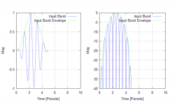
I thought some explanations might be helpful what is actually going on. So this is the shape of the excitation signal I'm using for these measurements. It's a short burst of 5 cycles of sinusoid modified by a shaped envelope. The picture shows the signal and it's envelope in linear and dB scale.
This signal is copied from the idea from Linkwitz.
The burst is short enough to give quite good resolution in time domain, and the shaped envelope helps to keep the spectral regrowth in minimum and the bandwidth in acceptable limit.
- Elias
Attachments
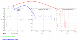
Here's the method I use to calculate the envelope peak magnitude and the envelope peak delay.
The left hand side shows the input signal envelope and the blue is the measured room response envelope at a particular frequency (56 Hz in this case). The peak point of the measured room response envelope defines the peak magnitude and peak delay as shown in the middle and right hand side pictures.
To get the freq responses as shown in the picture the input burst frequency is stepped in 1/12 octave intervals and the above is repeated.
Hope this helps")
- Elias
The left hand side shows the input signal envelope and the blue is the measured room response envelope at a particular frequency (56 Hz in this case). The peak point of the measured room response envelope defines the peak magnitude and peak delay as shown in the middle and right hand side pictures.
To get the freq responses as shown in the picture the input burst frequency is stepped in 1/12 octave intervals and the above is repeated.
Hope this helps
- Elias
Attachments
Conclusions at this far
Ok, some revolutionary conclusions are in order based on the measurement results so far
I divide the conclusions in three parts according the selected freq ranges.
* 20 Hz - 35 Hz:
1 a ) Monopole bass and dipole bass show identical room time response in all locations A - D.
In all cases the envelope closely follows the input signal envelope.
* 35 Hz - 100 Hz:
2 a ) Dipole shows clearly better room time response than monopole in all locations A - D.
2 b ) Monopole room time response is the most sensitive to placement A - D.
2 c ) Dipole room time response is less sensitive to placement A - D than monopole, but more sensitive than dipole line array.
2 d ) Dipole line array room time response is the least sensitive to placement A - D.
2 e ) Dipole line array room time response is almost identical to dipole room time response in all locations A - D. This is due the limited hight (1.5m) of the array and thus the array directivity in this freq range is not enough to improve the response over the dipole.
* 100 Hz - 1 kHz:
3 a ) Monopole has worse room time response than dipole or dipole line array.
3 b ) Dipole has better room time response than monopole but worse than dipole line array.
3 c ) Dipole line array has the best room time response over monopole and dipole.
3 d ) Monopole room time response is the most sensitive to placement A - D.
3 e ) Dipole room time response is less sensitive to placement A - D than monopole, but more sensitive than dipole line array.
3 f ) Dipole line array room time response is the least sensitive to placement A - D.
3 g ) When approaching 1 kHz monopole and dipole room time responses are getting similar. This can be due to increased directivity of the monopole and decreased directivity of the dipole because of cone and baffle size.
3 h ) At 1 kHz dipole line array still has the best room time response.
More conclusions to follow when they appear to my mind
- Elias
Re: OB line array vs. sealed
Hello,
Thanks! YES, when the first time I switched the signal to the dipole line arrays I was totally blown away I'm still looking for my hat! What can I say.. It sounds very detailed starting from low frequencies already. Many systems can sound detailed in high freqs, say above 1kHz, but lack the accuracy at lower freqs due to the room.
You are welcome. Well, I selected smallish baffle for the dipole because it is the only way to extend the constant dipole directivity freq range all the way to 1kHz. If you make the baffle too big then the driver is starting to act like a monopole which makes things only worse.
I think 'better' drivers may not be needed for an array. Cone excursion is small and nonlinearities usually not a problem. Selecting a driver with low stored energy is of course an advantage. Fortunately also some cheap drivers have low stored energy.
Hmm.. We can pretty much guess what happends for the room time response in this case if we have monopole line array: From the measurements of dipole and dipole line array (of 1.5m height) we can conclude they behave similarly at low frequencies 100Hz and below. So the case would be similar for a monopole and monopole line array, they would behave similarly at 100Hz and below. Then we also see from the measurements that monopole is much worse than dipole at 100Hz and below. So all in all monopole line array does not pay unless used at higher frequencies only, say above 200-300 Hz, and crossed over to dipole below that. But what's the point of using monopole at so high freqs when dipole will be better anyway?
If you find interest to build a monopole line array, let's compare the room time response measurements then
- Elias
Hello,
sendler said:Fascinating work with an excellent test signal/ analysis method. Were you surprised by the substantial superiority of the dipole line array? I had often thought to try that as it would seem a good solution to the increased volume displacement demands of open baffle.
Thanks!
YES, when the first time I switched the signal to the dipole line arrays I was totally blown away I'm still looking for my hat! What can I say.. It sounds very detailed starting from low frequencies already. Many systems can sound detailed in high freqs, say above 1kHz, but lack the accuracy at lower freqs due to the room. brianpowers27 said:THank you for posting your test results. I would like to raise a concern I have regarding the comparison between the various tests. I am concerned that by using different drivers and baffle widths you are ignoring the baffle's role in the equation.
I would not consider the comparison between dipole and dipole line array to be complete until you are using the same drivers on the same shape baffle.
You are welcome. Well, I selected smallish baffle for the dipole because it is the only way to extend the constant dipole directivity freq range all the way to 1kHz. If you make the baffle too big then the driver is starting to act like a monopole which makes things only worse.
sendler said:Yes, the advantage of the line array could be even bigger with better drivers.
I think 'better' drivers may not be needed for an array. Cone excursion is small and nonlinearities usually not a problem. Selecting a driver with low stored energy is of course an advantage. Fortunately also some cheap drivers have low stored energy.
sendler said:Now that I see the OB line array results look so good, it would be intersting to throw a box over the back to see the same set up running sealed.
Hmm.. We can pretty much guess what happends for the room time response in this case if we have monopole line array: From the measurements of dipole and dipole line array (of 1.5m height) we can conclude they behave similarly at low frequencies 100Hz and below. So the case would be similar for a monopole and monopole line array, they would behave similarly at 100Hz and below. Then we also see from the measurements that monopole is much worse than dipole at 100Hz and below. So all in all monopole line array does not pay unless used at higher frequencies only, say above 200-300 Hz, and crossed over to dipole below that. But what's the point of using monopole at so high freqs when dipole will be better anyway?
If you find interest to build a monopole line array, let's compare the room time response measurements then
- Elias
Great thread, Elias.
Did you measure these burst sequences directly or did you convolve the bursts with a measured impulse reponse? For convenience I now do mostly the latter after I had confirmed that it really gives identical measurements (unless I run into severe distortion issues).
- Klaus
Did you measure these burst sequences directly or did you convolve the bursts with a measured impulse reponse? For convenience I now do mostly the latter after I had confirmed that it really gives identical measurements (unless I run into severe distortion issues).
- Klaus
I really don't want to throw rain on your parade, but I really don't see the relavance of this. First, above about 300-500 Hz the perception issues are far more complex than you can show with your technique. Below 150 Hz no one who knows how to setup a sound system in a room is going to use a single sub, monopole, dipole or line array and multiple subs are going to work completely different than what you show. Between 150 Hz and say 300 Hz, I really don't know what you are showing means, but I really doubt that it is as simple as you seem to believe that it is. Perception issues are just not that simple.
Re: Conclusions at this far
Couldn't much of this have to do with energy storage from the differing formats rather than totally from interaction with the room?
In other words - what would a pressure-based dipole act like vs. a pressure-based monopole?
Also - how much of it is the interaction with the enclosure (or lack thereof)?
Elias said:Ok, some revolutionary conclusions are in order based on the measurement results so far
I divide the conclusions in three parts according the selected freq ranges.
* 20 Hz - 35 Hz:
1 a ) Monopole bass and dipole bass show identical room time response in all locations A - D.
In all cases the envelope closely follows the input signal envelope.
* 35 Hz - 100 Hz:
2 a ) Dipole shows clearly better room time response than monopole in all locations A - D.
2 b ) Monopole room time response is the most sensitive to placement A - D.
2 c ) Dipole room time response is less sensitive to placement A - D than monopole, but more sensitive than dipole line array.
2 d ) Dipole line array room time response is the least sensitive to placement A - D.
2 e ) Dipole line array room time response is almost identical to dipole room time response in all locations A - D. This is due the limited hight (1.5m) of the array and thus the array directivity in this freq range is not enough to improve the response over the dipole.
* 100 Hz - 1 kHz:
3 a ) Monopole has worse room time response than dipole or dipole line array.
3 b ) Dipole has better room time response than monopole but worse than dipole line array.
3 c ) Dipole line array has the best room time response over monopole and dipole.
3 d ) Monopole room time response is the most sensitive to placement A - D.
3 e ) Dipole room time response is less sensitive to placement A - D than monopole, but more sensitive than dipole line array.
3 f ) Dipole line array room time response is the least sensitive to placement A - D.
3 g ) When approaching 1 kHz monopole and dipole room time responses are getting similar. This can be due to increased directivity of the monopole and decreased directivity of the dipole because of cone and baffle size.
3 h ) At 1 kHz dipole line array still has the best room time response.
- Elias
Couldn't much of this have to do with energy storage from the differing formats rather than totally from interaction with the room?
In other words - what would a pressure-based dipole act like vs. a pressure-based monopole?
Also - how much of it is the interaction with the enclosure (or lack thereof)?
gedlee said:I really don't want to throw rain on your parade, but I really don't see the relavance of this.
First, above about 300-500 Hz the perception issues are far more complex than you can show with your technique.
Below 150 Hz no one who knows how to setup a sound system in a room is going to use a single sub, monopole, dipole or line array and multiple subs are going to work completely different than what you show.
Between 150 Hz and say 300 Hz, I really don't know what you are showing means, but I really doubt that it is as simple as you seem to believe that it is. Perception issues are just not that simple.
I think the relevance is rather obvious - to show if there is a significant difference other than simple deviations in amplitude. In this case higher levels of linear decay "hanging" in the room.
Considering the issues of "masking" at low freq.s - any lingering high amplitude signal is (IMO) bound to impact the perception of clarity at those freq.s and perhaps perceptually across the entire bandwidth.
While the issues of perception may be very complex (for any pass-band), this doesn't mean that what is shown doesn't have relevance. It may not be "relevant enough", but it's certainly a subject for thought - and at some point "relevance" may be more deeply investigated BECAUSE of this work.
People "who know how to set up a sound system" use a single monopole sub all the time. Not likely because they want to, but rather because that's the limitation they are stuck with. Note that for a single listener - a single monopole or dipole sub *immediately* behind this listener (with appropriate phase adjustment) can work exceptionally well for that one listener (even at higher freq.s approaching 100 + Hz).
I also don't think that at any time Elias is "definitively" stating conclusions. It doesn't appear to be a statement of: "this is what it is", rather more like: "this seems likely with what I have so far".
Hello Klaus,
I used the shaped tone burst as a real excitation signal fed to the speakers. It is true that the same results can be calculated from the impulse response (just make sure the impulse response is long enough to contain all the room reflections one likes to focus to).
I think the benefit of feeding the burst directly to the speakers is that one can listen the response at the same time while making the measurement! It is very revealing! One can detect all kind of phenomenas in addition to the normal amplitude level and room response, like resonances of the speaker cabinet or furnitures and also nonlinear distortion, if these are above hearing threshold. All this is unknown to the ear if one measures only the impulse response.
It is very informative to compare on the spot what the ear hears and what the measurement shows. I have found that this kind of burst test measurement correlates quite well what I can hear too.
The impulse response is mathematically correct (for a linear system) but the ear does not benefit from it. Only if the music would be an impulse.. But it's not
- Elias
KSTR said:Did you measure these burst sequences directly or did you convolve the bursts with a measured impulse reponse? For convenience I now do mostly the latter after I had confirmed that it really gives identical measurements (unless I run into severe distortion issues).
Hello,
The dipole line array I used for these tests is 1.5 m long vertical array of 8 pcs of 6.5" elements.
When comparing the measurements of the single dipole to the dipole line array it is seen that below about 100 Hz they behave almost identically. -> Thus one can conclude that dipole line array gives benefit to the room time response over the single dipole only when the length of the array is longer than about half of the wave length. In this case the 1.5 m corresponds about half wave length at 100 Hz.
Of course array of elements have other benefits like decreased nonlinear distortion. And array allows using 'cheaper' elements.
Well, propably those 18" elements do not play very high in frequency, maybe up to 100Hz-200Hz, so we are in the range where the array needs to be very long to give more directivity over the single dipole. But of course it will be slightly better than single driver anyway. If you make the array about 2-3 m long it will be very good around 100Hz.
For the bass array there should be no reason why horisontal would be different from vertical. I'm using vertical because it'll play over 1kHz.
- Elias
CLS said:Did you define line array? (or did I miss it?) Does it mean vertical array strictly? How about horzontal? I have 4 18" woofers on OB, all very close to floor and unevenly spaced. Does this count?
We are still waiting your data to prove your claims about multible subs
Have you done room time response measurements of your system?
- Elias
Have you done room time response measurements of your system?
- Elias
gedlee said:...
multiple subs
...
Re: Re: Conclusions at this far
Hello Scott,
The results shown are almost purely due to the room effects.
See for example the measured monopole response picture:
http://www.diyaudio.com/forums/attachment.php?s=&postid=1884495&stamp=1248117969
The left hand side shows the input and measured envelope (blue). One can see that at first the signal tries to come but then first reflections cancel the signal away and it does not follow the input envelope but then later arriving reflections over emphasize the response. This is due the monopole having simple too many reflections to all directions because the lack of directivity.
If we have directivity we have less first reflections and the room response envelope follows more closely to the input envelope.
Important to note that not all the reflections are so bad. The first reflections are the worst! So reflections please do come, but not yet! Wait for a while so I can first hear the music recording, and after that I may be willing to listen to reflections too!
The key is to minimise the first reflections in a time frame compared to periods, since the ear integration time is not constant with frequency. And to be able to do this at low freqs the source needs to have directivity.
- Elias
ScottG said:Couldn't much of this have to do with energy storage from the differing formats rather than totally from interaction with the room?
In other words - what would a pressure-based dipole act like vs. a pressure-based monopole?
Also - how much of it is the interaction with the enclosure (or lack thereof)?
Elias said:We are still waiting your data to prove your claims about multible subs
Have you done room time response measurements of your system?
- Elias
I don't know where you have been, but multiple subs is accepting extremely wide acceptance.
I would question the validity of "time response" for LFs in small rooms. It has no relavence and this has been shown. What we hear at LF, where the periods of the sound are greater than our ears averaging time, is the steady state. We do not hear LF transients, or "time response".
I use an impulse generated from a logsweep which is several minutes long. This captures everything. BTW I also listen to the impulse, slowed down to 1:5...1:50. Very revealing too, when it comes to judging the quality of the reverberant sound.Elias said:I used the shaped tone burst as a real excitation signal fed to the speakers. It is true that the same results can be calculated from the impulse response (just make sure the impulse response is long enough to contain all the room reflections one likes to focus to).
Well, I'm using shaped tone burst sequences for about ten years now, for charactising LF responses. In fact I made a nice CD of that wich was optimized for practical use in many regards, both in home listeneing setups and for smaller live club usage. So I completely agree that listening to bursts is way more revealing than using any other signal, for the LF range. Especially as you are free to walk around and look what happens.I think the benefit of feeding the burst directly to the speakers is that one can listen the response at the same time while making the measurement! It is very revealing! One can detect all kind of phenomenas in addition to the normal amplitude level and room response, like resonances of the speaker cabinet or furnitures and also nonlinear distortion, if these are above hearing threshold. All this is unknown to the ear if one measures only the impulse response.
It is very informative to compare on the spot what the ear hears and what the measurement shows. I have found that this kind of burst test measurement correlates quite well what I can hear too.
My signal shapes are a bit different, I use sequences of several cycles, like 20 or so (to have enough time to energize high-Q modes), with 2-3 cycles of raised cosine envelopes at beginning and end. This basic signal is repeated, with a continuously shrinking blank time between the busts. The blank time is either always a multiple of a cycle or an odd multiple of 1/2-cycle. This gives me two signal characteristics, one with continuous phase from burst to burst and the other with a polarity flip. From how the sound changes during these gaps I can learn about the character of the mode. I also use those two types in to L/R-polarity variants, one time simple mono the other with L=-R. This gives me four basic signal types which don't allow any modes to slip through (like those that cancel themselves when the speakers are in opposite polarity lobes of the mode).
Thes signals are available for download, but I have to write up an english documentation and have to check with the hoster if the traffic will pose a problem (as when I link to it from DIYaudio there sure will be a lot of traffic).
With the Farina logsweep method you get the disortion (for the chosen signal level), too.The impulse response is mathematically correct (for a linear system) but the ear does not benefit from it.
- Klaus
Very interesting Klaus!
Me too have the bursts on CD, it's very handy. I found that for home use for measuring speakers in the room the most suitable burst length is close to 5 periods. I've tried up to 10 period bursts but the temporal accuracy suffers because reflections mask it more.
I didn't catch how you listen to the impulse? You mean you first measure the impulse response and then play it back at slower speed? How you listen, with ear phones?
Yes. If the sweep is very slow it's easy to hear the room modes and constructional resonances as well as distortion. But sweep is not fun to listen!
I have a hardware sweep generator, but I found it's pain to my ears to listen to it I do use it to locate the exact resonanses by manual tuning the amplitude and frequency, for that purpose it's very good.
- Elias
Me too have the bursts on CD, it's very handy. I found that for home use for measuring speakers in the room the most suitable burst length is close to 5 periods. I've tried up to 10 period bursts but the temporal accuracy suffers because reflections mask it more.
KSTR said:BTW I also listen to the impulse, slowed down to 1:5...1:50. Very revealing too, when it comes to judging the quality of the reverberant sound.
I didn't catch how you listen to the impulse? You mean you first measure the impulse response and then play it back at slower speed? How you listen, with ear phones?
KSTR said:With the Farina logsweep method you get the disortion (for the chosen signal level), too.
Yes. If the sweep is very slow it's easy to hear the room modes and constructional resonances as well as distortion. But sweep is not fun to listen!
I have a hardware sweep generator, but I found it's pain to my ears to listen to it
I do use it to locate the exact resonanses by manual tuning the amplitude and frequency, for that purpose it's very good. - Elias
Elias,
The nice thing with an already recorded IR is that one can use any signal to covolve it with, so if I want to listen how your 5-period bursts sound like in my system I only need to convolve it and listen to it (not on the original system, of course), which I did. A problem I saw with such a short impulse is that at higher frequencies the round trip time is larger than the burst time, which means that you only get the the echo effect but not the effect of the mode buildup. With my signals you can clearly see the round trip time for the mode and also see the total time until the mode reaches equilibrium (something like 5 or more round trip times, for a typical higher Q mode). See attachment, for a higher order mode at 240Hz in my room, listen position at point where a boost results (Note: I've cut the central part of the wave to also show the decay. Bottom trace is stimulus). That's why I chose to have the bursts long enough to allow the mode to fully build up in the first place.
- Klaus
Yes, I record a long logsweep to have a good S/N-ratio, derive the impulse from it (by convolution with the inverse), and then play it back, using either headphones or on my nearfield monitors (I hate listen to headphones). When slow enough you can literally hear the floor bounce and the following reflections from the various surfaces, especially if there are slap echoes from undamped tricorners and such. Occasionally I also apply a reverse log envelope gain to the signal, to make the reverb tail louder to more clearly hear what's going on. Something you just don't clearly see in the impulse waveform (let alone a FR mag plot) and you also don't quite catch it when listening to a real-time impulse, unless the effect are very pronounced and/or one has a lot of experience in hearig these subtleties in realtime.Elias said:I didn't catch how you listen to the impulse? You mean you first measure the impulse response and then play it back at slower speed? How you listen, with ear phones?
Same with my test-signal CD (which also uses CD-text it the player can display that). The first signal is brown noise, the second a sweep (from 27.5Hz to 440Hz). When you find a problematic freq during the sweep then you just skip to about the track number corresponding to the current time of the sweep and can do more detailed analysis. The 97 burst tracks are staggered in semi-halftone steps (1/24 oct resolution).I have a hardware sweep generator, but I found it's pain to my ears to listen to it
The nice thing with an already recorded IR is that one can use any signal to covolve it with, so if I want to listen how your 5-period bursts sound like in my system I only need to convolve it and listen to it (not on the original system, of course), which I did. A problem I saw with such a short impulse is that at higher frequencies the round trip time is larger than the burst time, which means that you only get the the echo effect but not the effect of the mode buildup. With my signals you can clearly see the round trip time for the mode and also see the total time until the mode reaches equilibrium (something like 5 or more round trip times, for a typical higher Q mode). See attachment, for a higher order mode at 240Hz in my room, listen position at point where a boost results (Note: I've cut the central part of the wave to also show the decay. Bottom trace is stimulus). That's why I chose to have the bursts long enough to allow the mode to fully build up in the first place.
- Klaus
Attachments
Hello,
This is a very good picture and tells many things. As I see the time axis the signal starts at 0.1 and steady state begins at 0.2. So there is a room response transient state duration of 100ms, that's about 20 periods at the measurement freq.
Obvious question considering this thread is have you done any tests comparing different directivity speakers to investigate if the transient state duration or slope is changing?
I don't know what was the speaker directivity for this test, but according to my measurements there should be a noticeable difference when using higher directivity source in this freq range of 240Hz.
Then one can think how this transient state is perceived. I've noticed in my listening tests that even if I change the envelope over the couple of periods only at the starting of the burst there is clearly perceived difference. In this room the transient lasts 20 periods, so that should be easily perceivable.
How do you hear it?
Another thing is of cource the transient decay, but there should be no questions about it's perception: It is easily perceivable - That's why they add artificial reverberation to studio recordings
- Elias
KSTR said:See attachment, for a higher order mode at 240Hz in my room, listen position at point where a boost results
Hi,
Of course at the real listening spot and with my normal listening conditions (doors&windows open, mostly) it is not that bad.
What I learn from this that things happening in the modal range of a real room are nothing intuitive at all and very hard to predict and track down what really is happening. Best thing of course is to avoid the exitation in the first place with directional speakers located at the right places and ranging from dipole to cardioid and anything in between (hypercardioid looks very promising to me), for upper bass and midrange. For lower bass multiple subs (DBA included) looks easier to me to get best results.
- Klaus
No, not with this setup. Those were standard monopole 3way-floorstanders, and 240Hz happen to be about the xover between 8" woofer and 4" midrange. But I have listening experience with dipoles and know what difference it makes, especially in the bass range.Elias said:Obvious question considering this thread is have you done any tests comparing different directivity speakers to investigate if the transient state duration or slope is changing?
I don't know what was the speaker directivity for this test, but according to my measurements there should be a noticeable difference when using higher directivity source in this freq range of 240Hz.
Just as it looks like, the buildup/decay is clearly audible. But I have nastier freq spots than this, at 320Hz for example the buildup/decay is strange, sort of a hick-up. During buildup the hickup effect is pretty well masked, but on decay it really sounds funny, one can hear it.Then one can think how this transient state is perceived. I've noticed in my listening tests that even if I change the envelope over the couple of periods only at the starting of the burst there is clearly perceived difference. In this room the transient lasts 20 periods, so that should be easily perceivable.
How do you hear it?
Of course at the real listening spot and with my normal listening conditions (doors&windows open, mostly) it is not that bad.
What I learn from this that things happening in the modal range of a real room are nothing intuitive at all and very hard to predict and track down what really is happening. Best thing of course is to avoid the exitation in the first place with directional speakers located at the right places and ranging from dipole to cardioid and anything in between (hypercardioid looks very promising to me), for upper bass and midrange. For lower bass multiple subs (DBA included) looks easier to me to get best results.
- Klaus
Attachments
- Status
- This old topic is closed. If you want to reopen this topic, contact a moderator using the "Report Post" button.
- Home
- General Interest
- Room Acoustics & Mods
- Measured monopole and dipole room responses