Good measure for safety, but then I would start to take out until its unsafe. Less is more. The proper clamping is the major guard here IMO. Have to watch its self noise contribution though.
OK, so here's the prototype. I know, it's a mess.
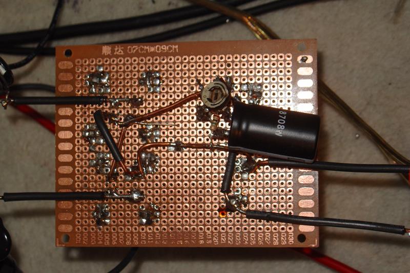
First, the rectifier diodes + gyrator filter.
back
and front
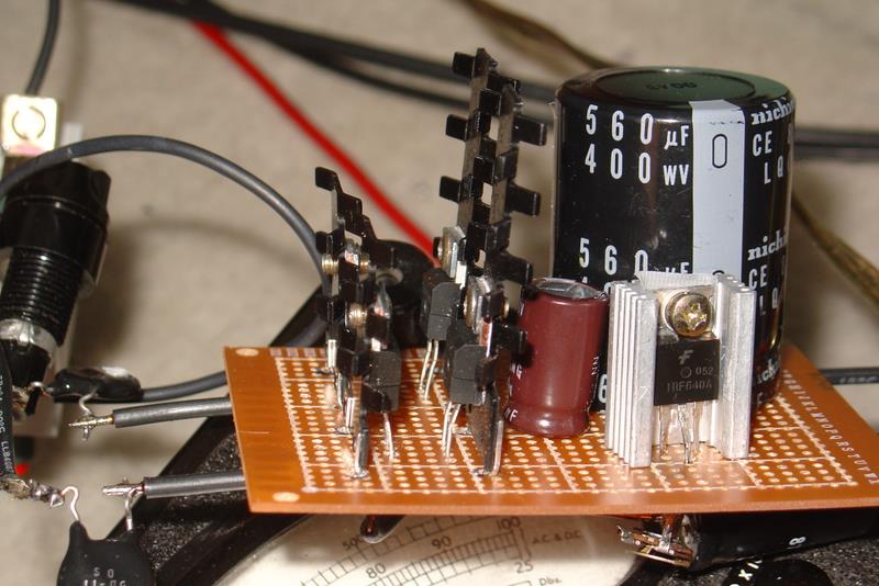
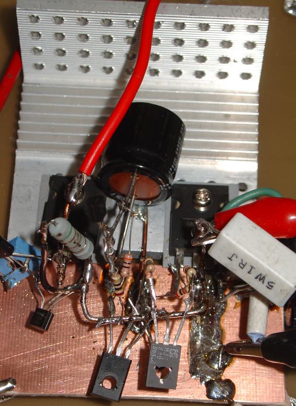
the regulator top. Next to the left mosfet is the trimmer mounted on the dn2540 . Next to the dn2540 is the mpsa42. The big cap in between the mosfets is across the zeners which are hard to see in the mess in the middle. Those two TO-126 transistors in the middle are the mje350 and mje340. The big white 1R resistor is in series with the load, so I can keep an eye on the current.
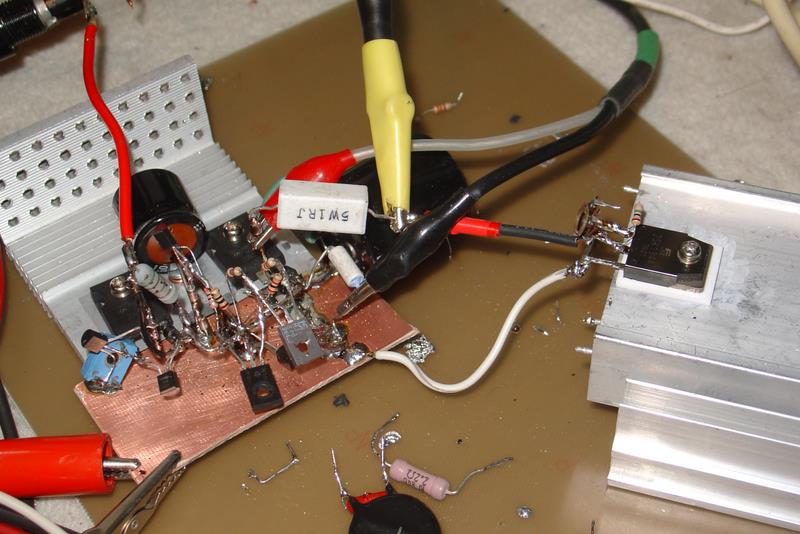
In this pic the load can be seen better. Below the large white resistor is a smaller 0R1, in series with the source of the shunt mosfet, which I'm using to monitor the shunt current. The load is a 2sk1944 900V mosfet, with a 1M across D-G, and a 100K variable resistor across G-S which I adjust for the current I want as load.
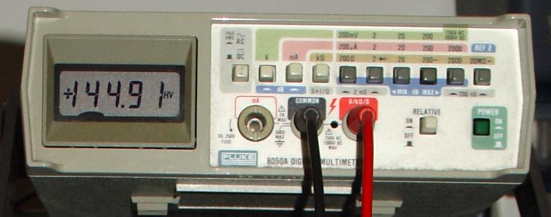
You know how zeners are not exactly the advertised value? I used two 75V zeners in series. Unless the Fluke is all wrong about the measured value.
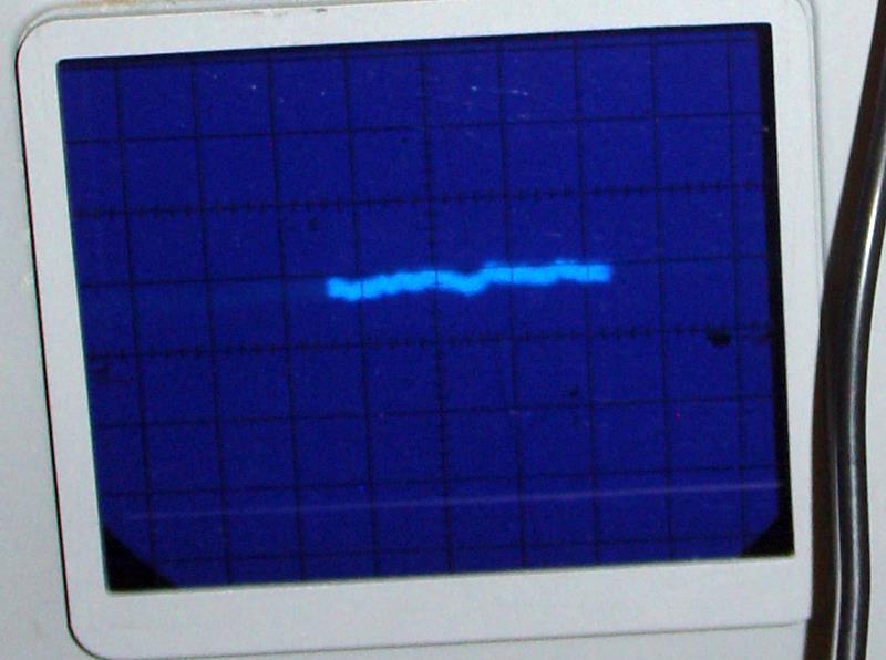
Now this was hard to catch with the camera. The scope was set on 500uV/div.
That's all for now.
First, the rectifier diodes + gyrator filter.
back
and front
the regulator top. Next to the left mosfet is the trimmer mounted on the dn2540 . Next to the dn2540 is the mpsa42. The big cap in between the mosfets is across the zeners which are hard to see in the mess in the middle. Those two TO-126 transistors in the middle are the mje350 and mje340. The big white 1R resistor is in series with the load, so I can keep an eye on the current.
In this pic the load can be seen better. Below the large white resistor is a smaller 0R1, in series with the source of the shunt mosfet, which I'm using to monitor the shunt current. The load is a 2sk1944 900V mosfet, with a 1M across D-G, and a 100K variable resistor across G-S which I adjust for the current I want as load.
You know how zeners are not exactly the advertised value? I used two 75V zeners in series. Unless the Fluke is all wrong about the measured value.
Now this was hard to catch with the camera. The scope was set on 500uV/div.
That's all for now.
Iko,
Could you add the circuit that includes the gyrator - quite interested in these strange things, particularly when combined with Cmultipliers!
Could you add the circuit that includes the gyrator - quite interested in these strange things, particularly when combined with Cmultipliers!

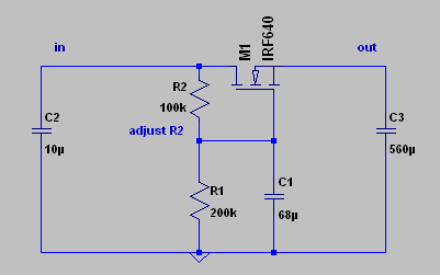
James, it's a very simple thing that I used, for lack of a good choke 
R2 is adjustable, started with about 100R then increased the value until I got the voltage drop and filtering that I wanted.
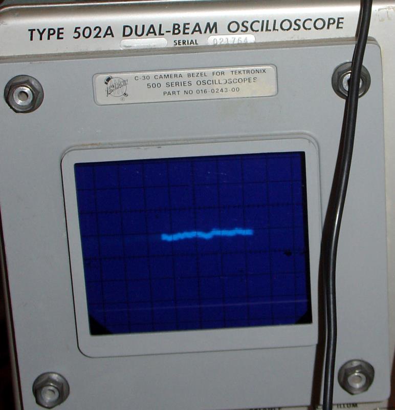
Thanks Anatoliy, I love my tube tek 502a 😀 yup... what's not to like, real dual beam, 100uV/div sensitivity, dual differential input.
R2 is adjustable, started with about 100R then increased the value until I got the voltage drop and filtering that I wanted.
Thanks Anatoliy, I love my tube tek 502a 😀 yup... what's not to like, real dual beam, 100uV/div sensitivity, dual differential input.
Excellent. I love dead bug construction. Smells genuine DIY. Keep C3 off the sink. You compromise it and you ware it out with heat. Good to use a Mosfet gyrator for a choke, best value for money and some delay. We had a thread with Anatoly about gyrator goodness for other purpose, as constant voltage anode load not too long before. The NTC to the far left of 2nd picture is a good soft start measure too.
Salas said:Excellent. I love dead bug construction. Smells genuine DIY. Keep C3 off the sink. You compromise it and you ware it out with heat. Good to use a Mosfet gyrator for a choke, best value for money and some delay. We had a thread with Anatoly about gyrator goodness for other purpose, as constant voltage anode load not too long before. The NTC to the far left of 2nd picture is a good soft start measure too.
There is some magic in building a new design, it reminds me of the time I used to develop B/W photos... when the image starts appearing on paper like a ghost. So no matter how messy it gets, I still like it, but I know it's not everyone's cup of tea. Yes, C3 is badly set on the sink, which is too small for this project anyway. I'll redo the circuit on perf board after some more tests, for the headphone amp, then it'll have a proper layout.
Good eyes, you spotted the NTC. In fact I use two of them, one on each secondary lead; 5D-11 is the component. I was afraid of the inrush current. Do you know anything about how an NTC might affect the sound?
My opinion is, gyrators here are suboptimal. Unlike choke, they can't store an energy. But what is drawn, is a R-C filter with a source follower, it is much better thingy here than a gyrator. Hyrator with the capacitor in series may be tuned on some frequency to form a LPF, but actually what is needed, a dynamic resistance on all frequencies, from zero to megaHertzs, as low as possible.
Anatoliy, you say that a choke is what you prefer in a filter?
I lack a good choke at the moment, but I wanted to have some filtering to test the regulator.
BTW, since I'm lucky to have your attention for a second here, may I ask for your opinion on the schematic on post 412?
http://www.diyaudio.com/forums/showthread.php?postid=1898022#post1898022
I am a beginner and most experienced people here don't usually waste their time with my schematics. I appreciate any advice.
ikoflexer said:Anatoliy, you say that a choke is what you prefer in a filter?
Not always. Chokes help to utilize mains power without creating current peaks.
I lack a good choke at the moment, but I wanted to have some filtering to test the regulator.
And you did it!
BTW, since I'm lucky to have your attention for a second here, may I ask for your opinion on the schematic on post 412?
http://www.diyaudio.com/forums/showthread.php?postid=1898022#post1898022
I am a beginner and most experienced people here don't usually waste their time with my schematics. I appreciate any advice.
It looks quite fine from my first sight, but I would limit base current of a current sensing transistor, and protected gates by Zeners: if MOSFET starts oscillating it may destruct gate insulation.
Wavebourn said:
It looks quite fine from my first sight, but I would limit base current of a current sensing transistor, and protected gates by Zeners: if MOSFET starts oscillating it may destruct gate insulation.
You mean a base resistor of 50-100R on Q2 and zeners on G-S pins?
Edit: well, I just modified the schematic using your suggestion. Thanks!
Thanks Iko, for the cct a few post back.
I might just see if it works akoy(!) on the rails for the testbed DAO headamp and the poor suffering F3 amp - I have extra volts on the transformers for just this sort of thing - Cmultipliers, 'low/high shunt current' Salas shunt Regs, floating rectifiers, and now a gyrator!
I might just see if it works akoy(!) on the rails for the testbed DAO headamp and the poor suffering F3 amp - I have extra volts on the transformers for just this sort of thing - Cmultipliers, 'low/high shunt current' Salas shunt Regs, floating rectifiers, and now a gyrator!
ikoflexer said:Good eyes, you spotted the NTC. In fact I use two of them, one on each secondary lead; 5D-11 is the component. I was afraid of the inrush current. Do you know anything about how an NTC might affect the sound?
If in line with a mighty trafo in a large A/B amp they modulate a bit. But with constant current as with the shunt, no worries. They are blind to the load.
Anatoly is referring to ''punch through clamping'' as I have mentioned before. If you use 12V Zeners its about 3.5uV self noise they are going to put across G,S. Your call.
jameshillj said:Thanks Iko, for the cct a few post back.
I might just see if it works akoy(!) on the rails for the testbed DAO headamp and the poor suffering F3 amp - I have extra volts on the transformers for just this sort of thing - Cmultipliers, 'low/high shunt current' Salas shunt Regs, floating rectifiers, and now a gyrator!
Gyrators or capacitance multipliers are a good and economic measure, not real chokes, but they could be overkill with the psrr our stuff attains. In general you hear what is before those shunts a lot less. And that saves $.
Salas said:
Anatoly is referring to ''punch through clamping'' as I have mentioned before. If you use 12V Zeners its about 3.5uV self noise they are going to put across G,S. Your call.
Yes, I thought about that too. But if the circuit has reached its operating point the voltage across G-S should be below the conduction point of the zener, so the only current going through it should be tiny (leakage), so the usual zener noise should not apply, right?
Theoretically yes, but I don't trust the little buggers.😀
P.S. Sometimes the jinx can go negative so they usually clamp them with 2 Zeners back to back or a Zener and a blocking diode.
P.S. Sometimes the jinx can go negative so they usually clamp them with 2 Zeners back to back or a Zener and a blocking diode.
When about listening to the headphone amp plus shunt? What headphones you use? Don't get surprised if you see some Headwize guys trying it out if you get to nail it as a whole. Which is highly possible you got it IMHO.😉
Salas said:When about listening to the headphone amp plus shunt?
Ah, I don't know if you followed my DHT headphone amp adventure, because this regulator is for that one. I finally got sound out of that topology, DHT+p-channel mosfet+OT. Didn't connect it to the regulator yet. As for the other tube headphone amp, not tried with the regulator either. But soon, I hope, now that the shunt works.
What headphones you use?
Sony mdr-v6... I know, very plebeian. But they sound good to me (very precise).
Don't get surprised if you see some Headwize guys trying it out if you get to nail it as a whole. Which is highly possible you got it IMHO.😉
If it works well some people might like it, yes. I know I'll nail it for myself, just a matter of time. Other people will have to judge for themselves. We'll see.
Ot consideration on tube vs SS
HI Salas I don't know if is the right place ,but I like to know your vision.
my fist impression on 300b are mix , details in incredible in the midhigth ,bass are deep and round ,in general can be dry some time, good dinamic but on rock the SS are more powerfull and smooth the tube have a little compression ,this a low volume
like the tube work on separate manner bass to mid to hight ,the SS more uniform
thanks
Normal comparison account you give. If you want tube rock drive check out Tubelab. George has them with powerdrive and maxed out. If they don't play Depeche Mode and full tilt rock he just does not make them.😎 He gives proof pcbs to construct them on so no buzzes. You can enjoy the silence.
OT off.
OT off.
- Home
- Amplifiers
- Power Supplies
- Simplistic mosFET HV Shunt Regs