Hello all!
Wanted to lower sound volume on my DAC, it has discrete output. What resistors must I change and on what value? For example, now listen on 12-13 hours, but wanted on 16-17.
you use J2 and J5 one the center board IV, the gain go up!
thanks
Thanks you kmajjo, I have been trying to solve this problem, like forever. At first it worked fine, then it slowly start to not respond, until it totally not responding at all. I have been trying to get Quanghao to help me out, but he is not responding. Would you know what could be causing the problem? Maybe it needs to be reprogram or something? There is nothing wrong the remote physically, its perfetly fine. If you can give me one to try out, I would appreciate it.
Alex
im wrong
Last edited:
Hi,
I have the DAC-END R (ES9018). I am having problem with my remote. Its no longer working, I changed the battery, but its not responding. Can anybody out there help me with this? Quanhao, can you please help me with this? Everything is working fine, except the remote. Please help, anybody....
Alex
please sent to me your adress again, i sent you new board remote!
thanks
quanghao
Another question: how much output impedance in discrete output stage? Wrote that
But how much is this "low". Somebody measured it?very low output impedance
Another question: how much output impedance in discrete output stage? Wrote that But how much is this "low". Somebody measured it?
yes, 10R with oput IRF610 SE!
thanks
What is the output impedance of the stage with lundahl transformers?
Is that stage able to drive 4.5 meter balanced cable connected to a 100 kohm power amp input? (Dac output voltage is enough for full power)
Hello, Sandor,
From Output Transformers Explained
An output transformer has no impedance by itself (ignoring primary inductance/resistance ). It simply reflects the impedance load on the secondary back to the primary.
The impedance ratio is the square of the turns ratio, which is also the square of the voltage ratio, as shown in the following equation:
Zp/Zs = (Np/Ns)2 = (Vp/Vs)2
For example, if you have a transformer designed for 4.3K : 8 ohms, you can apply a 1 volt AC signal across the secondary 8 ohm winding, and you should see 23.18VAC across the primary, which corresponds to a 23.18:1 voltage ratio or a 537.5:1 impedance ratio, which would reflect an 8 ohm load back as 4.3K.
As you can see, the transformer has no inherent impedance, it merely reflects the load impedance back to the primary.
Br
Jacky
Items for sale
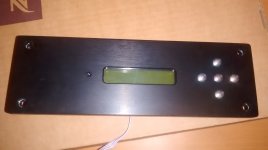
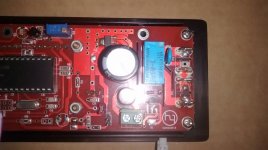
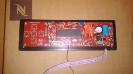
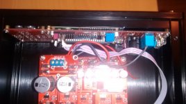
Hi. Unfortunately for me, I am having to sell my Version 1 DAC. I have absolutely enjoyed it, but decided to have it re-housed in a smaller chassis for various reasons. The plan was to have the DAC rehoused in a 210mm wide chassis with a separate chassis having the transformers and a raspberry pi. There was also supposed to have been another chassis with amp modules. Unfortunately, the person who was supposed to have built all this for me, messed it all up and never quite completed the build! The back panels on the new chassis were a complete mess and I eventually had to pull the plug.
The modules have been working fine. Rather than try and rebuild them into the original chassis, I decided have decided to sell them. I am planning to sell the original chassis as well.
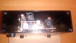
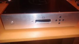
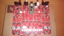
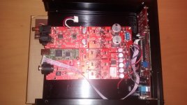
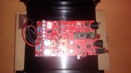
Pictures are enclosed. Lot 1 would be the DAC boards including the audio boards, controller with standby function and standby relay, 2 transformers - one to power the DAC / audio boards and a second transformer for the standby function. Lot 2 would be the original Quanghao chassis in silver designed for the Version 1 controller.
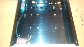
I have decided to throw in the "new" chassis as well - as you can see the front has been cnc'ed to accommodate the controller. There is no power switch as the power switch is meant to be in the second chassis housing the transformers and RPi, and was meant to work with the standby function. The audio boards were supposed to be placed above the DAC, but this would mean that the AES connector on the DAC board would have to be removed. Alternatively, the audio boards can be mounted upright, but thid does not leave much room for the power connector. Obviously, if the chassis is not required, I will simply get rid of it! Incidentally, the second chassis to accommodate the power supply is also available if someone wants it! The measurements are 210mm width, 220mm depth and 70mm height. They are of reasonable quality, I think although the feet are glued on and completely rubbish! The back panels are available but probably quite useless. I think it would be best to flat pack the Lot 1 chassis.
I am open to offers. Please PM me with an offer. If agreeable, I will accept payment by PayPal or can set up a listing on eBay for payment, if preferred. I live in the UK, and estimate the courier and insurance to cost approximately £15. Should be cheaper if the chassis is not required. Happy to send more pictures if required.
Hi. Unfortunately for me, I am having to sell my Version 1 DAC. I have absolutely enjoyed it, but decided to have it re-housed in a smaller chassis for various reasons. The plan was to have the DAC rehoused in a 210mm wide chassis with a separate chassis having the transformers and a raspberry pi. There was also supposed to have been another chassis with amp modules. Unfortunately, the person who was supposed to have built all this for me, messed it all up and never quite completed the build! The back panels on the new chassis were a complete mess and I eventually had to pull the plug.
The modules have been working fine. Rather than try and rebuild them into the original chassis, I decided have decided to sell them. I am planning to sell the original chassis as well.
Pictures are enclosed. Lot 1 would be the DAC boards including the audio boards, controller with standby function and standby relay, 2 transformers - one to power the DAC / audio boards and a second transformer for the standby function. Lot 2 would be the original Quanghao chassis in silver designed for the Version 1 controller.
I have decided to throw in the "new" chassis as well - as you can see the front has been cnc'ed to accommodate the controller. There is no power switch as the power switch is meant to be in the second chassis housing the transformers and RPi, and was meant to work with the standby function. The audio boards were supposed to be placed above the DAC, but this would mean that the AES connector on the DAC board would have to be removed. Alternatively, the audio boards can be mounted upright, but thid does not leave much room for the power connector. Obviously, if the chassis is not required, I will simply get rid of it! Incidentally, the second chassis to accommodate the power supply is also available if someone wants it! The measurements are 210mm width, 220mm depth and 70mm height. They are of reasonable quality, I think although the feet are glued on and completely rubbish! The back panels are available but probably quite useless. I think it would be best to flat pack the Lot 1 chassis.
I am open to offers. Please PM me with an offer. If agreeable, I will accept payment by PayPal or can set up a listing on eBay for payment, if preferred. I live in the UK, and estimate the courier and insurance to cost approximately £15. Should be cheaper if the chassis is not required. Happy to send more pictures if required.
Attachments
-
 IMG_20170602_212223914.jpg300.1 KB · Views: 316
 -
 IMG_20170602_220025263.jpg323.6 KB · Views: 134
 -
 IMG_20170602_215838983.jpg313.9 KB · Views: 174
 -
 IMG_20170602_214536328.jpg501.6 KB · Views: 171
 -
 IMG_20170602_213411969.jpg260.8 KB · Views: 146
 -
 IMG_20170602_213351223.jpg531.1 KB · Views: 157
 -
 IMG_20170602_213336893.jpg463.2 KB · Views: 294
 -
 IMG_20170602_213149369.jpg485.6 KB · Views: 294
 -
 IMG_20170602_213139542.jpg563 KB · Views: 309
 -
 IMG_20170602_212256195.jpg505.6 KB · Views: 306
Hello,
Sorry i have trouble(MY HQ reference DAC ES9018S)
USB Input signal sometime it is lock but sometime it nolock.
Why it occurs like this and how to adjust?
thanks.
81552 - Sendvid
Change resistors to Takman carbon and filter capacitors to polystyren. BURSON V6 AS OPAMPS.Any mod for up the audio level ouput?
Cheers
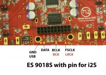
Use the header block which is provided to connect an Amanero board. Pin assignment is as per the Amanero spec sheet -Anybody knows how input I2S signal into this DAC?
3 I2S DATA / DSD1
4 I2S BCLK / DSD CLK
5 I2S FSCLK / DSD2
Use the pins on the opposite side of the header block for grounds - 13, 14, 15.
Alternatively, in front of the Amanero header block are 10 holes, in 2 rows of 5. These carry the same connections, but in a different order:
2 BCLK
3 DATA1
4 DATA2 (FSCLK)
If you solder a header here, you can use a standard ribbon cable/plug assembly for connection, and this pin order is more likely to match other I2S output devices, than the Amanero pin order does.
Use the header block which is provided to connect an Amanero board. Pin assignment is as per the Amanero spec sheet -
3 I2S DATA / DSD1
4 I2S BCLK / DSD CLK
5 I2S FSCLK / DSD2
Use the pins on the opposite side of the header block for grounds - 13, 14, 15.
Alternatively, in front of the Amanero header block are 10 holes, in 2 rows of 5. These carry the same connections, but in a different order:
2 BCLK
3 DATA1
4 DATA2 (FSCLK)
If you solder a header here, you can use a standard ribbon cable/plug assembly for connection, and this pin order is more likely to match other I2S output devices, than the Amanero pin order does.
Thanks guys, Quanghao image is also helpful.
Alex
linuxfan; hi please see image! thanks quanghao[/QUOTE said:Looks like the board was designed to use some kind of female connector, can anyone recognize what type of connector it is that will go into those 5 holes?
Alex
- Status
- This old topic is closed. If you want to reopen this topic, contact a moderator using the "Report Post" button.
- Home
- More Vendors...
- Quanghao Audio Design
- DAC-END R (ES9018) full assembled board - version 2