Hi Andrea,1) It is necessary reduce the current on shunt changing R4 and R5 from 10 ohm to 15 ohm because now the temperature of the second smd transistor is very high. Quanghao can send you the 4 x 15ohm smd resistors to make this simple correction.
2) Eliminate also R9 and R10 in the +15V and -15V shunt.
3) Add a 47uF or 100uF capacitor in parallel to the original 47uF on the 1.2V analog (L & R) near the jump to eliminate the little oscillation.
I am wating for my dac. Do I need to ask these modifications from Quanghao or this will be the actual version ?
Hi Andrea,
I am wating for my dac. Do I need to ask these modifications from Quanghao or this will be the actual version ?
Same question! I would also like some spare buttons. Please let me know how much to pay.
1) It is necessary reduce the current on shunt changing R4 and R5 from 10 ohm to 15 ohm because now the temperature of the second smd transistor is very high. Quanghao can send you the 4 x 15ohm smd resistors to make this simple correction.
2) Eliminate also R9 and R10 in the +15V and -15V shunt.
3) Add a 47uF or 100uF capacitor in parallel to the original 47uF on the 1.2V analog (L & R) near the jump to eliminate the little oscillation.
Since I have my DAC, I have a different question.
Are we going to get a "kit" of the parts required to rework the DAC?
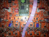
Can you circle the affected parts on a picture of the DAC?
I am not using the opamp board, so I think I have fewer parts to replace.
For item 3), can you show a picture of a reworked board?
Thanks
Randy
Add a 47uF or 100uF capacitor in parallel to the original 47uF on the 1.2V analog (L & R) to eliminate the little oscillation at 14KHz.
OK, thanks.
Let clear the points: we have to change R4/R5 to 10 ohms for preventing shunts to melt, add 47µF to stop an oscillation and change the firmware. For a finished product...
Can you precise how to connect the PIC programmer on the display board (what connector) as I found the views for the hardware mods? What is the PIC reference?
A friend of mine has a PIC programmer and the know how to use it so this part will be the easier for me.
I think it will be find to receive the new components (ie 4 10 ohms smd and 2 47µF Oscon).
we have to change R4/R5 to 10 ohms
You need to remove R10/R11 too.
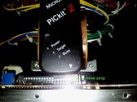
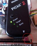
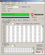
Firmware upgrade with Pickit2
Move both the 2 jumps in the second position.
You can do this operation with the DAC switched on.
After flash disconnect the Pickit 2 and move the jumps in the original position.
Move both the 2 jumps in the second position.
You can do this operation with the DAC switched on.
After flash disconnect the Pickit 2 and move the jumps in the original position.
Attachments
Last edited:
Op-amp module corrections
1) It is necessary reduce the current on shunt changing R4 and R5 from 10 ohm to 15 ohm because now the temperature of the second smd transistor is very high. Quanghao can send you the 4 x 15ohm smd resistors to make this simple correction.
2) Eliminate also R9 and R10 in the +15V and -15V shunt.
1) It is necessary reduce the current on shunt changing R4 and R5 from 10 ohm to 15 ohm because now the temperature of the second smd transistor is very high. Quanghao can send you the 4 x 15ohm smd resistors to make this simple correction.
2) Eliminate also R9 and R10 in the +15V and -15V shunt.
Attachments
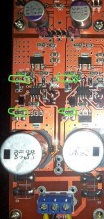
1) It is necessary reduce the current on shunt changing R4 and R5 from 10 ohm to 15 ohm because now the temperature of the second smd transistor is very high. Quanghao can send you the 4 x 15ohm smd resistors to make this simple correction.
2) Eliminate also R9 and R10 in the +15V and -15V shunt.
3) Add a 47uF or 100uF capacitor in parallel to the original 47uF on the 1.2V analog (L & R) near the jump to eliminate the little oscillation.
Quanghao, is it possible to apply above correction before send the dac to me. I'm afraid of sms. Thank you
")
Hi NicMac,
Those R-30 transformers can be configured for 115vac or 230vac, they have dual primaries of 115vac, connected in series is for 230 vac.
I've connected the yellow-blue wire together for 230vac, the red and brown goes to the socket, see pictures.
Regards,
Danny
Those R-30 transformers can be configured for 115vac or 230vac, they have dual primaries of 115vac, connected in series is for 230 vac.
I've connected the yellow-blue wire together for 230vac, the red and brown goes to the socket, see pictures.
Regards,
Danny
Thanks danny_66,Hi NicMac,
Those R-30 transformers can be configured for 115vac or 230vac, they have dual primaries of 115vac, connected in series is for 230 vac.
I've connected the yellow-blue wire together for 230vac, the red and brown goes to the socket, see pictures.
Regards,
Danny
I got the complete assembled DAC so I will have to check how it was factually wired up.
Hi Palmito,
I have the LL1684 hooked up like in this schematic.
Attention: the pin layout is from the bottom view (where you can see the pins), not like in the LL1684 pdf where it is the component view (where you see the label).
Regards,
Danny
I have the LL1684 hooked up like in this schematic.
Attention: the pin layout is from the bottom view (where you can see the pins), not like in the LL1684 pdf where it is the component view (where you see the label).
Regards,
Danny
Attachments
Last edited:
- Status
- This old topic is closed. If you want to reopen this topic, contact a moderator using the "Report Post" button.
- Home
- More Vendors...
- Quanghao Audio Design
- DAC-END R (ES9018) full assembled board