Hello Jogi,
already have done next upgrade. 1 uF Jensen CU-oil to second stage and 0,22 Jensen to paypass to anode voltage. Results are very good. More dynamics and sub bass.... it is logical result. As Next step i will add Duelund CAST PIO to first stage....
According to Your proposed shematics -- do is it really good , if the signal is going trough 3 capacitors? Are You compared this amplifier with another D3a project?
Hi, it is 2 capacitors, the ecc288 is the line stage part and does not belong to the phono stage. Output after the second D3a...
I compared both circuits and liked the second one better, it is more linear and dynamic.
I also built a supply with tube rectifier (AZ1, very nice), which I found to be more musical and >magic<. But this is more a matter of taste.
I compared both circuits and liked the second one better, it is more linear and dynamic.
I also built a supply with tube rectifier (AZ1, very nice), which I found to be more musical and >magic<. But this is more a matter of taste.
Tube rectifier is a point... I have experiences , that the tubes are more analog ...but also more round like 2 D and not so fine ..like 3D , as the transistor / diodes rectifier can give. It of course depend of waht type of tube and capacitors we uses... but my taste was last times going to not tube rectifier... If it is not a secret, what amplifier, loudspeakers and cables you are using ? Also signal source is important?
Interesting, I had opposite impressions, the tube rectifier is more 3d and spacious. But I use CLCLC Filter, then Salas Shunt, and a nice AZ1 with mesh anode.
But this is probably different in power amps with higher current demand.
At the moment speakers are old Cabasse 3 way with alnico magnets, amp is either EL84 PP or Tpa3116 class D. But when I built the phono amp, it was Quad ESL57.
TT is a double platter Lenco with upgraded bearing , and a Hadcock arm; sometimes I use MM cartridge, sometimes my AT33ptg with Silk MC transformers. Very good table indeed...
Cables are there too
Hello,
maybe there is point, how to do Filter. I have experiences with CLC jet...
I am using Verity Amadis speakers last time, and amplifier is ASR Emitter I , Emitter II and tube amplifiers from Audolici ( A25M and I50 Swing ). Cables are been PAD Corvus series and many another higher range from XLO and Synergistich Researsh. I have compared Phono sound with Heed Audio Thesis ( only transistor ) amplifier and WHEST and Tron amplifiers....
A question for our friend Andrea ( Audiodesign ).
Looking a the schematics of the original phonostage, something puzzles me.
In both the first and second tube the anode resistor is 11k and B+ is 200V. With a cathode resistor of 50R, a basic calculation, with the D3a curves at hand, tells us that the standing current for that configuration is around 12mA. Therefore, the voltage drop across the anode resistors is 0.012*11000= 132V
The tension at the anode is 200-132= 68V. and in the cathode we have 0.012*50= 0.6Volt
My question is : what’s the point of dropping 132V across the anode resistors when a phono stage needs very little room for voltage swinging. The output is usually 2 Vrms, at most. 20 or 30 V peak to peak would be enough.
For instance, with B+=100V and a plate resistor of 2k5 we’d have the same anode tension on the plate (70V aprox), the cathode (0.6V) and of course the same plate standing current - 12mA. We’d have 30 volt across the plate resistors, which is more than enough for our purpose and we’d spare a lot of wasted heat on these resistors. compared to the original configuration with B+=200V. Also, the components of the PSU: diodes, capacitors, mosfets (if any) will be less stressed, We can also use capacitors and transistors rated for less voltage.
Andrea, the only explantion that I can guess is that you had already that 165VAC R-core transformer and you use it for convenience ?.
If somebody wants to build the phono-stage from scratch, wouldn’t be better to use a 80 to 100VAC PSU Trafo instead of 165 VAC ?
THISHello when can I expect the drawings? I have done a large part and now want to do the metalwork.
Thank you in advance.
thanks
Attachments
THIS
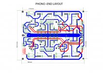
The L and R grounds should be separated, at least up to the power supply connector.
Andrea, if you read well my post, I wasn't saying to put less voltage on the anode. I was saying to keep the same voltage and current, lowering the B+ tension and the value of the plate resistors in order to spare wasted heat in the mentioned resistors and stress less the PSU components.Artur5,
Tubes sound better with high voltage and distortion is lower with high voltage.
You can work also with 20V on anode but the result is not the same.
As far as the tube is concerned, it would work on the same electrical conditions ( same tension on anode and cathode, same standing current )
Think they are not enough. If I am comparing to high end transistor amplifier –there are more powerful sub- bass.
Please tell about your experiences with this amplifier.
Hi There
I have been using mine off an on for many years. I Also felt that the bass was a bit low from my turntable so recently I revisited the design and actually put it on a Function generator and an oscilloscope to measure the RIAA curve.
Sadly what i found was that at 50hz the amplfication was 4db down from what it should be according to the RIAA curve.
The simple truth is that the cathode resistor (50ohm) and a 270uF capacitor in parralel with it attenuates <100hz frequencies too much.
I experimented with different resistor sizes and larger capacitors (up to 1000uf) all of them pushing up bass responce. But in the end settles on using a Infrared led in place of the 50ohm and 270uF cap.
I like the idea of removing the Capacitor. The LED changes the cathode voltage up the 0.5V cathode voltage to 1.15V
BUT
There is SO much more bass! And using the function generator and oscilloscope i measure correct RIAA curve to within 1db.
With the 22K resistor and 210Vdc B+ I measured 105V accross resistor wchich calcualtes to just less than 10mA bias through valve.
I was very close to changing 22K resistor to 10mA current source but decided to rather use with 22K and LED for the time being.
Very similar circuit for D3a found here:
AudioRoundTable.com: Group Build => RIAA preamp project
It is clear from the circuit diagram that JOGI post that bass responce will be MUCH better due to using 390 ohm with 470uF on cathode.
50 ohm with 270uF attenuates bass FAR to much.
Last edited:
Sorry @tangmonster, but biasing the D3a with 9.5mA is not the best choice IMHO. The original design is biased aprox. at 12mA, which will give less distorsion, although I'd preferred 14-15 mA for better sound.
Besides, it makes little sense that the RIAA error has much to do with the cathode resistor/capacitor. The tube is not in the RIAA network. The bass drop for a 50ohm/270ufarad combo on the cathode should be very small at 50 Hz -1dB maybe.
The design you mention uses the D3a in a very different configuration : grid 3 to anode instead of cathode, grid 2 to anode trough a 100R resistor vs. directly to anode and also uses higher bias current ( 11mA. )
Last edited:
biasing the D3a with 9.5mA is not the best choice IMHO. The original design is biased aprox. at 12mA, which will give less distorsion, although I'd preferred 14-15 mA for better sound.
I agree, My plan is to use it for a while and possibly lower anode resistor to make bias current higher. I measured 0.55V over the original 50ohm resistor which calculated to 11mA. I agree if i look at the d3a pdf load lines that 15 looks more linear.
it makes little sense that the RIAA error has much to do with the cathode resistor/capacitor. The tube is not in the RIAA network.
Again i have to agree, The 270uf cap has 0% to do with the RIAA network, BUT it has VERY much an effect of Valve gain due to adding negative feedback at lower frequencies.
If you calculate the resistance of 50ohm and 270uF in parralel at various frequencies is:
1khz = 0.007ohm
100hz = 0.7ohm
50hz = 2.6ohm
20hz = 12.9ohm
2.6ohm and 12ohm is a large persentage of 50ohm and you can clearly see in the math how it will have an effect on bias/gain at these frequencies.
The higher resistance at lower frequencies WILL give feedback to the cathode voltage which WILL have an effect on gain.
I measured a somewhat large effect. I upped the capacitor to 1000uf which helped with lower frequencies but not enough.
The design you mention uses the D3a in a very different configuration
Again I agree. I was simply refering to the 470uf in parralel with 390 ohm which gives much lower impedance to low frequency than 50ohm in parralel with 270uf.
Last edited:
Hello Jogi, a little late but now I try to complete this project. I have the boards populated with anything than tube shockets after these years. Following your advice, I don't use the matching power supply board supplied, instead, I have SSHV2 stored for too much time. Also I have AZ1 with mesh plates. please lets ask for advice, what inductance value on two chokes? and also don't know what value in three capacitors (I have spare 10 and 20 henry ASC oil cans.)
Also I need order the power transformer. Please lets me know what voltage in secondary B+ to power such a power supply.
Thanks in advance, Jordi.
Also I need order the power transformer. Please lets me know what voltage in secondary B+ to power such a power supply.
Thanks in advance, Jordi.
After long time this project was started I am completing mine. I just noticed that the D3a triode strapped is unstable and oscillates badly. As soon as I connect the output capacitor it goes mad. I noticed that the screen grid is hard wired to the anode without a resistor. Could be that the cause? Did anyone have this issue?
Revisiting D3A Phono
Hi,
I would like to know if anyone is still visiting this forum, I have the phono stage that I put together about 6 years ago but had no success in getting up and running. I then took ill for some time but now I would like to try and get it up and running. I must admit I donot have much experience in electronics, relying basically on what my father passed on to me 50 years ago..lol hope someone can come to my rescue and steer me in the right direction.
Regards
Jerry.
I have the phono stage that I put together about 6 years ago but had
no success in getting up and running.
Ok, post the schematic and some photos. What have you done to check the circuit,
and what test equipment do you have?
- Home
- More Vendors...
- Quanghao Audio Design
- OLD THREAD Hi-end phono preamplifier by Andrea Ciuffoli