Have you read my previous post ?
These are the Kand Audio modules to implement a costant current generator instead of normal anodic resistors, see link
K & K Audio - Lundahl Transformers, audio DIY kits and more
These are very different as characterictics and sound to the dynamic current generator tested with bad results in my 2a3 cheap.
New 2A3
Hello Andrea,
What value of the output capacitor and Rload are you using? What's the minimum voltage of the output capacitor? Is 200V OK?
Regarding the jumper on the DAC board, is it correct to hard wire pin 1 & 3 and leave pin 2 untouched?
Thanks for your response in advance.
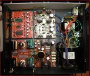
housing
What value of the output capacitor and Rload are you using? What's the minimum voltage of the output capacitor? Is 200V OK?
Regarding the jumper on the DAC board, is it correct to hard wire pin 1 & 3 and leave pin 2 untouched?
Thanks for your response in advance.
housing
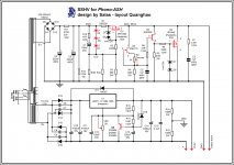
I have a Vcc about 267V
Va set by the trimmer to 180V
so Vccs = 267 - 180 = 87V
Rk = 470ohm
Vk = 6.7V
Ik = 6.7 / 470 = 14mA
Pcss = 87 * 2 * 14mA = 2.5w
I am confused. In quanghao's PDF file, Va is 90V and Vk is 3.8V.


One more thing, what's the total current consumption of the IV stage per channel?
Last edited:
I don't really know about the sonic difference but I hear no Difference...
About the filter I read somewhere that filter should be R=1K C=47nF... CMIIW
Yes, the data sheet says so.
Hello Andrea,
What value of the output capacitor and Rload are you using? What's the minimum voltage of the output capacitor? Is 200V OK?
Regarding the jumper on the DAC board, is it correct to hard wire pin 1 & 3 and leave pin 2 untouched?
Thanks for your response in advance.
housing
200v is not ok.
you should always spec the output cap to be B+ with an extra margin. you need 300v or more caps. if something goes wrong you want the output cap to survive. You do not want 260v going to your next piece of kit!
Andrea is using a different operating point for the CCS. Using a CCS allows you to pick different operating points due to the horizontal load line created (Constant Current, so horizontal). The plate voltage is then just set by the grid bias.
for normal (not using the extra CCS PCB) then the 90v plate voltage is more suitable.
Last edited:
200v is not ok.
you should always spec the output cap to be B+ with an extra margin. you need 300v or more caps. if something goes wrong you want the output cap to survive. You do not want 260v going to your next piece of kit!
Andrea is using a different operating point for the CCS. Using a CCS allows you to pick different operating points due to the horizontal load line created (Constant Current, so horizontal). The plate voltage is then just set by the grid bias.
for normal (not using the extra CCS PCB) then the 90v plate voltage is more suitable.
Hello Adam,
Thanks for your explanation. I think I understand now.
AD 1865 N-K Group buy
Very sorry for a little distortion
For anyone who wants get The Real AD1865N-K
Please Order in this Group buys, just need 8 pcs order for 30
http://www.diyaudio.com/forums/group-buys/164592-ad-1865-n-k-lets-do-again-4.html#post2164277
Thank you
Very sorry for a little distortion
For anyone who wants get The Real AD1865N-K
Please Order in this Group buys, just need 8 pcs order for 30
http://www.diyaudio.com/forums/group-buys/164592-ad-1865-n-k-lets-do-again-4.html#post2164277
Thank you
Hi, mouser, digikey, newark, farnell are out of stock. Can I use IRFP250PBF instead IRFP240PBF ?
RS components
code 541-0660
Hi, mouser, digikey, newark, farnell are out of stock. Can I use IRFP250PBF instead IRFP240PBF ?
No, too high Ciss and gfs to match the other side. Look for IRFP244, IRFP340.
Thanks pop music, Salas, I have to order some missing parts for my other projects. I found IRFP244PBF on mouser. I will let you know how it works out in few days.No, too high Ciss and gfs to match the other side. Look for IRFP244, IRFP340.
Fred,
where you don't see "filters and bypass caps" ?
Andrea,
Sorry, I meant L1 and L2 was omitted as well as C4, C5, C9 and C10.
Would this heater power supply for the phono preamp applicable to the DACend? The 2.2ohms resistors and the bridge rectifier are too hot, can't stand it. This might be better that the original one. Please advise.
Attachments
Last edited:
- Status
- This old topic is closed. If you want to reopen this topic, contact a moderator using the "Report Post" button.
- Home
- More Vendors...
- Quanghao Audio Design
- OLD THREAD DAC End by Andrea Ciuffoli