Problematic I/V stage PCB
Hi quanghao,
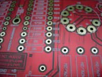
I looked at ksnider1's I/V stage PCB that's clean with crispy copper traces and examined mine that arrived this morning. Why is mine so dirty and masked by something unknown, and the ground plane near R32/R33 is extremely deformed and distorted?

Hi quanghao,
I looked at ksnider1's I/V stage PCB that's clean with crispy copper traces and examined mine that arrived this morning. Why is mine so dirty and masked by something unknown, and the ground plane near R32/R33 is extremely deformed and distorted?
Attachments
Last edited:
...and the ground plane near R32/R33 is extremely deformed and distorted?
Mine is also deformed in that place, looks very similar.. There have been some other quality issues also, with Salas output pads if I remember right..
Does any member finish his 5687 I/V stage with the Simplistic Mosfet HV Shunt designed by quanghao? How much current and voltage should it be set?
Very good question, as I am waiting for salas board. As far as I remember, 50V + are required for the shunt to work.
So which transformer secondary voltage do we need, does anyone have an idea?
Cheers,
Juergen
Nice work Ksnider1!
Very neat and tidy.
Thanks, I'm waiting for Salas shunt PCB for DAC now. I hope it's on the way by now.

Just sharing
An externally hosted image should be here but it was not working when we last tested it.
My friend uses Nelson Pass D-1 (replacement for Supply + IV Stage) for my DAC End 2.
But it hasn't worked well. He said the problem is on D-1.
(He'll find what really happened later)
Sound output ( Right and Left channel) isn't at the same level.
After replacing IRF610, previous problem is gone...
now DAC sings equal volume at right & left channel
After 1 hours play few songs, the result (compare with just DAC+Salas Shunt):
soundtage get wider
thick vocal
low and high get more extend
But..... voice sounds a little bit stiff. Need more time to break in?
Nice. Seems D1's I/V is an alternative to the tube I/V.
Thanks. Would like to hear further progress.
Thanks. Would like to hear further progress.
After replacing IRF610, previous problem is gone...
now DAC sings equal volume at right & left channel
After 1 hours play few songs, the result (compare with just DAC+Salas Shunt):
soundtage get wider
thick vocal
low and high get more extend
But..... voice sounds a little bit stiff. Need more time to break in?
I have altered my unit so that it is now using Welborne's PS10 power supply. It is regulated and uses no electrolytics. 267 volts to I/V board with 105V on the plates. I have listened for a couple of hours and believe the DAC has more punch and dynamics. Could me my head playing tricks but I am going to keep it this way for now.
Enjoy
Bob
Enjoy
Bob
Hi CustomHT,
I have the same transformer as yours, R80-36. I haven't connected yet since I'm still waiting for parts that I ordered.
This is how I will connect it
You have 2 center tap 3.15V/3A per winding, Gray, Black Gray
You have 1 center tap 2.5V/3A per winding, Blue, Brown, Blue
To make it 8.15V for the heater filament, you only need the 2 Blue wires, ignore the Brown wire just insulate the end of it. That gives you 5Vac/3A. Then connect one of the blue wires, to whichever 3.15V center tap you want to use, to Gray wire and the black wire will be 0V reference. Measure it with the voltmeter and if you don't get 8.15V, you might want to reverse the connection of black and Gray, as what housing had mention earlier. It might be out of phase. You were also asking if you can parallel the 3.15V winding. I think you can but this will become 6A which I don't recommend.
In regards to the 260Vac, I think you can parallel the winding to achieve the maximum current rating, tie up Green and Green wire and orange will be your 0V reference.
Let's consult with the veterans here. Guys, correct me if I'm wrong. I'm just trying to help CustomHT. I know he asked this question like 3 times already and nobody had given him a detailed answer of the transformer connection.
Thanks,
Fred
Thanks for you advice..
I've managed to get the 9v input right now, but I'm thinking I may have something wrong on the 260Vac side (maby in the IV power supply?) as I've tried both green / orange and violet / orange which both show required voltages when not connected to the IV stage power supply. Once connected to the power supply the r-core trannie starts humming and the power supply is not outputing any voltage, so turned it off quickly..
Any suggestions?
CustomHT,
Did you read my posts, especially #1417?
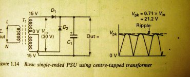
Yes I did, but I didnt fully understand what you ment when you said "use 2 diodes as a full wave rectifier"
you cant parallel the 260, it is centre tapped, not dual secondaries. You are just shorting it. HOpefully the secondary survived, just connect one of the 260v and the CT as 0.
I thought I had been using the CT? or am I getting confused?
The trannie is 260v (green) 230V (violet) 0v (Orange) 230V (violet) 260v (green).. I had been using the green and the orange wire for 260V?
Is this wrong?
Cheers in advance.
Simple question:
Can I use the DA103C transformer instead of the DA101C ?
DA103C Murata Power Solutions Transformers
The recommended one is not available.
This one from Silk will also work ?
Pulse Transformer for D/A convertor
the ratio is 1:1 what other features are important ?
Thanks,
Davide
Can I use the DA103C transformer instead of the DA101C ?
DA103C Murata Power Solutions Transformers
The recommended one is not available.
This one from Silk will also work ?
Pulse Transformer for D/A convertor
the ratio is 1:1 what other features are important ?
Thanks,
Davide
Yes I did, but I didnt fully understand what you ment when you said "use 2 diodes as a full wave rectifier"
Back to the basics
Attachments
CustomHT,
I don't have the regulator board, I have the HV shunt supply PCBs only.
Don't populate the 4 HV rectifiers and the 4 snubber capacitors on your board. Instead solder the center tap to a plate-thru' via connected to the -ve pole of C5 (100uF/450V) and the rectified HV to a plate-thru' via connected to the +ve pole of C5.
In such case, you can use the full 200mA capacity of the transformer.
Last edited:
hav you got any pics bob?
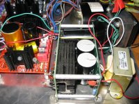
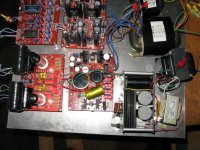
Hopefully these help. As you can see I'm still getting the 6V from the IV PS board. When I settle on final arrangement I'll put it all in a box.
Best
Attachments
- Status
- This old topic is closed. If you want to reopen this topic, contact a moderator using the "Report Post" button.
- Home
- More Vendors...
- Quanghao Audio Design
- OLD THREAD DAC End by Andrea Ciuffoli