The secondary for the filaments should be 8v 3A instead of 9v 1A.
and the 2 x 2.2ohm 3w resistor should be 2.2ohm 5w
3A seems high. are the regulators really that lossy?
I am going to order a customer toroid for this. It will work out cheaper than buying several R-cores.
Are these specs right
HT 0-230 @ 0.15 ampsanh dang ban la chat nhe
filament 0-9 @ 3A
salas1 0-12 @ 0.5A
salas2 0-12 @ 0.5A
salas3 0-12 @ 0.5A
THat is Ok
But R-cores 3 A is not good! not enough mA, because it is less, I see that!
yes. if you went the ebay Rcore route then you'll need three transformers. Shipping would get very expensive.
I had a quote from a british firm for £75 for a custom toroid.
I just Pm'ed a guy from the ukraine for a price, i get back to everyone with the result if favorable.
I had a quote from a british firm for £75 for a custom toroid.
I just Pm'ed a guy from the ukraine for a price, i get back to everyone with the result if favorable.
Yes, 165V is too low.
In the DAC End ver. 1 are necessary only 200V dc because all the power supply voltage go on tube anode.
In the DAC End ver. 2 we must use 265-275V to get a low distortion because many voltage are lost on anode resistors and on the anode there are about 180v.
See in previous page my choice for the transformers.
Here another good source for OS-CON
V.A. Hi Fi www.VocativeAudio.com The advanced Hi-Fi shop in China-Hong Kong
If you are searching a good custom trasformer manufactor I suggest the Italian Bartolucci
Ricerca e Sviluppo - Bartolucci Transformers - Products List - Power Transformers Toroidal
The price and the characteristics are very interesting.
I have payed more the 2 Chine r-core.
Ricerca e Sviluppo - Bartolucci Transformers - Products List - Power Transformers Toroidal
The price and the characteristics are very interesting.
I have payed more the 2 Chine r-core.
To get the best performance by this DAC project it is necessary use on DAC output module a 200ohm MK132 Caddock resistor.
For all the other resistor on the signal path has been considered good a parallel of two normal 1% metallic oside resistor with inverted phase to compensate some of their inductance.
Also the four 2w resistors must be connected with invereted phase (colors).
For all the other resistor on the signal path has been considered good a parallel of two normal 1% metallic oside resistor with inverted phase to compensate some of their inductance.
Also the four 2w resistors must be connected with invereted phase (colors).
Power transformers - idea
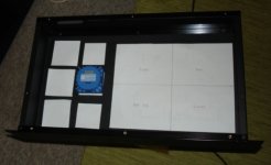
In my project I will use the following 6 caged PCB potted transformers (easy to find, compact and doesn't look messy):
1) 30VA PCB toroid 240pri 9+9sec parallel connected to 2) 9+9 parallel to get 240VAC for HT. (PRI-SEC-SEC-PRI)
3) 30VA (same as 1) PCB toroid 240pri 9+9sec parallel for DC HEATER
4) 10VA PCB toroid 240pri 9+9sec parallel to SALAS DIGITAL
5) 10VA PCB toroid 240pri 9+9sec parallel to SALAS ANALOG +5
6) 10VA PCB toroid 240pri 9+9sec parallel to SALAS ANALOG -5
Attachments
Last edited:
re 1) have you tried this before, i know a lot of people dont recomment it stating various issues.
also is 10va enough for the salas shunts? there are pretty inefficient. salas recommends 30va if i remember correctly.
As long as you respect the transformer voltages it is ok. There is a loss though by pumping back to the second transformer. If you use lower voltages on the second is bad, the transformer saturates, gets hot etc. But in this case I use identical transformer.
I'll let you know; tomorrow I try to load the transformers.
Apelizzo,
are you sure to have found a cheaper solution using all these separated transformers ?
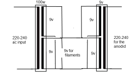
In any case use a 220:9+9 100w for the filaments and to drive a 9+9:220 50w to get also the 220V ac of anodic voltage is ok
I thought about like you said. I see if I can find another transformer, but $50 more o less... this project is good. All separate shunts why not a few $ more for transformers. I love mono design.
Make your own transformer
ALTERNATIVE: do your own transformer. It's FUN. Low voltage just few turns!!
You can use two toroids:
Step 1: buy the first one 220-240 primary 24V secondary at least 150VA
Step 2: rip the 24V winding off around 10 turns at the time don't cut the wire.
Step 3: Peel the enamel insulation and measure the voltage with multimeter
Step 4: Repeat Step 2 and 3 until you reach around 10V.
Step 5: Write down the total number of turns you took off the core and divide 14V (24V-10V) voltage drop by the number of turns you ripped off then multiply by 10. That's is close to the number of turns you need to do for the new 4 windings on top of the existing.
Step 6: buy the second toroidal transformer 240Pri 9+9V sec 50VA
Step 7: measure the voltage of the secondary with no load. Should be over 9V (better measure with load as both transformer have different regulation)
Step 8: adjust the secondary of first transformer to match the secondary of the second transformer. Adjust with turns.
Step 9: buy four lengths of insulated copper wire for transformer same thickness and length of the one you ripped off.
Step 10: wind the four lengths of wire to the core together one by one as is more convenient for you. How? put first the wire on a round wood stick that can all go in and out the centre of the core and start sewing, then do the second , third and fourth. Be careful do not damage the enamel protection around the copper wire. Do not use metal tools for winding or do sharp bends to the wire.
Step 11: mark all the wires and test the voltage and adjust till you match the secondary of the second transformer. Cut the wires short as required after you obtained the wanted voltages
Step 12: connect the first 9V secondary to the secondary of the second transformer as per the picture published by Audiodesign so you step up the voltage for the tube anodes.
Step 13: connect the remaining four independently to Heater, Salas +5D, +5A, -5A
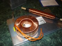
Example below of one I made for 280V, over 1400 turns!! For this little ding ding dong dong baby Single Ended 3W ampli, Lovely detailed sound
ALTERNATIVE: do your own transformer. It's FUN. Low voltage just few turns!!
You can use two toroids:
Step 1: buy the first one 220-240 primary 24V secondary at least 150VA
Step 2: rip the 24V winding off around 10 turns at the time don't cut the wire.
Step 3: Peel the enamel insulation and measure the voltage with multimeter
Step 4: Repeat Step 2 and 3 until you reach around 10V.
Step 5: Write down the total number of turns you took off the core and divide 14V (24V-10V) voltage drop by the number of turns you ripped off then multiply by 10. That's is close to the number of turns you need to do for the new 4 windings on top of the existing.
Step 6: buy the second toroidal transformer 240Pri 9+9V sec 50VA
Step 7: measure the voltage of the secondary with no load. Should be over 9V (better measure with load as both transformer have different regulation)
Step 8: adjust the secondary of first transformer to match the secondary of the second transformer. Adjust with turns.
Step 9: buy four lengths of insulated copper wire for transformer same thickness and length of the one you ripped off.
Step 10: wind the four lengths of wire to the core together one by one as is more convenient for you. How? put first the wire on a round wood stick that can all go in and out the centre of the core and start sewing, then do the second , third and fourth. Be careful do not damage the enamel protection around the copper wire. Do not use metal tools for winding or do sharp bends to the wire.
Step 11: mark all the wires and test the voltage and adjust till you match the secondary of the second transformer. Cut the wires short as required after you obtained the wanted voltages
Step 12: connect the first 9V secondary to the secondary of the second transformer as per the picture published by Audiodesign so you step up the voltage for the tube anodes.
Step 13: connect the remaining four independently to Heater, Salas +5D, +5A, -5A
Example below of one I made for 280V, over 1400 turns!! For this little ding ding dong dong baby Single Ended 3W ampli, Lovely detailed sound
Attachments
Last edited:
Low voltage tubes?
Can't low voltage tubes like ECC82, ECC86 or 6SL7GT be used in the place of the high voltage ones? Of course with changing the values of some resistors and the PSU of course.
Excuse my question if it's stupid as I don't have any experience with tubes...
Can't low voltage tubes like ECC82, ECC86 or 6SL7GT be used in the place of the high voltage ones? Of course with changing the values of some resistors and the PSU of course.
Excuse my question if it's stupid as I don't have any experience with tubes...
Last edited:
yes it can, but it would need a redesign of the PSU (i would forget using the PS pcb, unless you want to keep the filament supply section) and then as you say, changing values.
if you are worried about the voltage.... read read read, then bite the bullet and do a high voltage project.,
if you are worried about the voltage.... read read read, then bite the bullet and do a high voltage project.,
- Status
- This old topic is closed. If you want to reopen this topic, contact a moderator using the "Report Post" button.
- Home
- More Vendors...
- Quanghao Audio Design
- OLD THREAD DAC End by Andrea Ciuffoli