Guanghao,
You still didn't reply my questions about the prices.
How do you expect people to send you money when they don't know the exact amount they should send?
I repeat my questions:
As I understand, the prices are:
PCB- DAC END = $15
PCb Salas shunt for DAC=15
PCB- I/V stage = $15
PCB- Supply for I/V = $15 ( Now i dont have it, i make it later, you can use Salas shunt for IV stage)
no! i need 50$ for:
1 PCb DAC + 1 PCb Salas shunt for DAC + 1 I/V stage + shiping + free paypal.
Supply for I/V you can waite me some day later!
thank you!
Quanghao
This is very confusing.
Please post here exactly which PCBs you have and their prices, a detailed list of the PCBs and the price of each PCB. Also, the expected date of availability and the price of the PCB that you don't have right now.
Without it it's impossible to make an order.
i am using 11r (3 * 33r).
my guess is, 3r the tranformer is stuggling and 20r+ there isnt enough shunt current for the regulator to be optimal.
anymore than 20r and i cant adjust to 5.5v
So It was a right assumption, current was robbed with not enough left to the shunt Mosfet? Wasn't tested for current consumption as a an original total system it seems. Super reg Stax style shunts aren't free feed series. They will not just provide beyond CCS. Not difficult to grasp, but forgotten.
It works, perfect. I will have my mates round later to assess the sound, as i'm far too biased  .
.
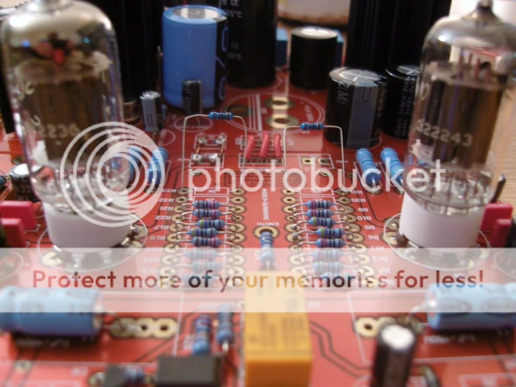
No really, it does sound great. The only criticism is the temp of the 2.2r (which has been discussed) and the temp of the 2 ic's on the I/V supply board, however i have them on massive heatsinks, so apart from those things which are easily overcome, it's been relatively easy to build. I followed the designs bit for bit except i used 2x27r on the digital shunt and i bridged both 2k and 1k at R11 on the I/V supply.
I need some time to assess the sound, and consider the reliability, which i will of course report back with.
Thanks to everyone for your help, or input into the great DAC.
.No really, it does sound great. The only criticism is the temp of the 2.2r (which has been discussed) and the temp of the 2 ic's on the I/V supply board, however i have them on massive heatsinks, so apart from those things which are easily overcome, it's been relatively easy to build. I followed the designs bit for bit except i used 2x27r on the digital shunt and i bridged both 2k and 1k at R11 on the I/V supply.
I need some time to assess the sound, and consider the reliability, which i will of course report back with.
Thanks to everyone for your help, or input into the great DAC.
no, i need 50$ for:
1 PCb DAC + 1 PCb Salas shunt for DAC + 1 I/V stage + shiping + free paypal.
Supply for I/V you can waite me some day later!
thank you!
Quanghao
Hi Quanghao,
Let me know when I can send 50 USD to your paypal account.
best wishes
It works, perfect. I will have my mates round later to assess the sound, as i'm far too biased
No really, it does sound great. The only criticism is the temp of the 2.2r (which has been discussed) and the temp of the 2 ic's on the I/V supply board, however i have them on massive heatsinks, so apart from those things which are easily overcome, it's been relatively easy to build. I followed the designs bit for bit except i used 2x27r on the digital shunt and i bridged both 2k and 1k at R11 on the I/V supply.
I need some time to assess the sound, and consider the reliability, which i will of course report back with.
Thanks to everyone for your help, or input into the great DAC.
Good stuff. if you have heatsinks on the salas shunts, i would be tempted to solder another 27r in parallel to the two already there.
Joshua_G!
Now those PCB stay in my house!
PCB DAC
PCB-Salas shunt for DAC
PCb-I/V stage
So i like you use The Simpler Simplistic Design by Salas for the I/V stage
the price:
1 PCb DAC + 1 PCb Salas shunt for DAC + 1 I/V stage + shiping + free paypal.
$ 50.
Do you understand ??
Quanghao
noizas
You cane sent now. Do not forget write nick name on diyaudio.com in to the pay pal
thank!
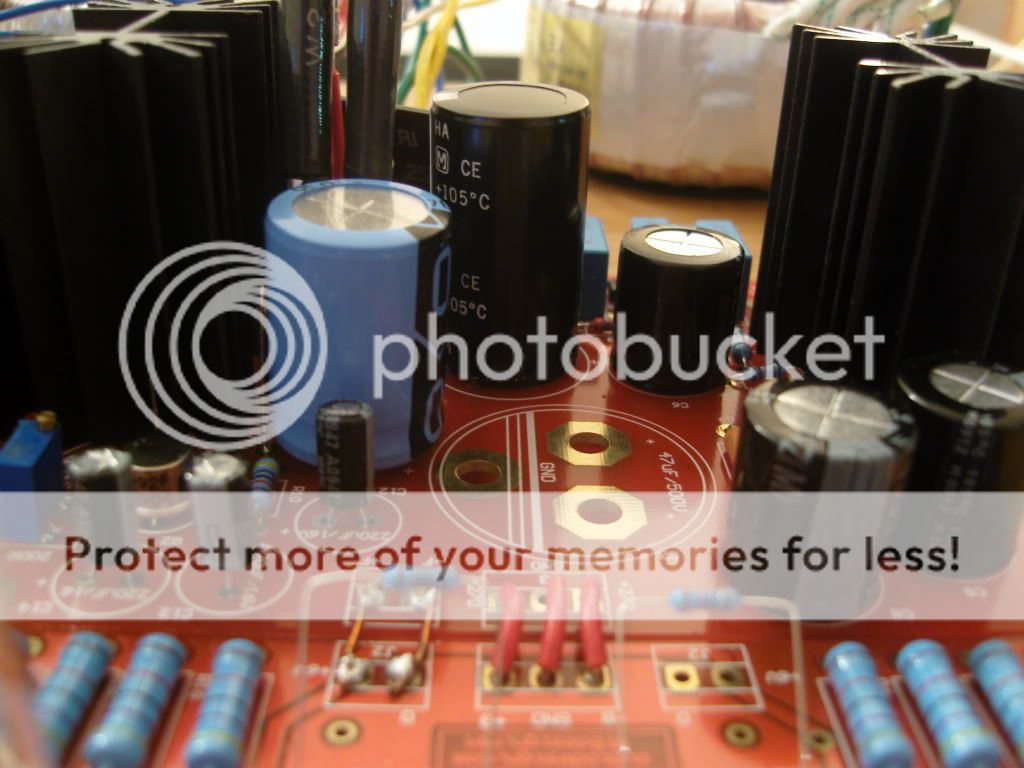
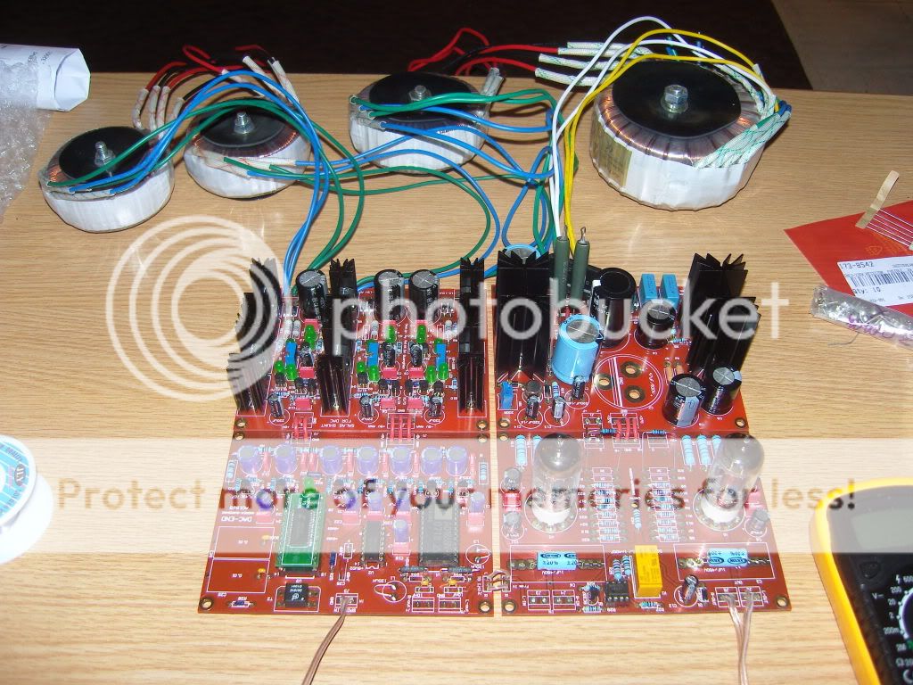
Here's a few for you. I have just gone for any old thing to start with, then later i can play with to my hearts content to get what i like.
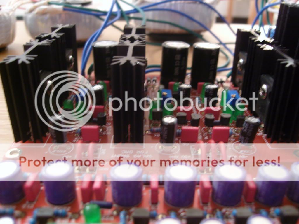
I have found something very annoying though, when there is silence i get a quiet twitching noise. It's completely random and sounds like a quiet clicking noise, very fast and random. It does it even when i unplug my input and the unit is on, which leads me to think it's on the analog side of the chip, or it's in the I/V stage.
Anyone take a guess what it is?
Just like a scratching noise present all the time, but when music is playing it's not audible.
Last edited:
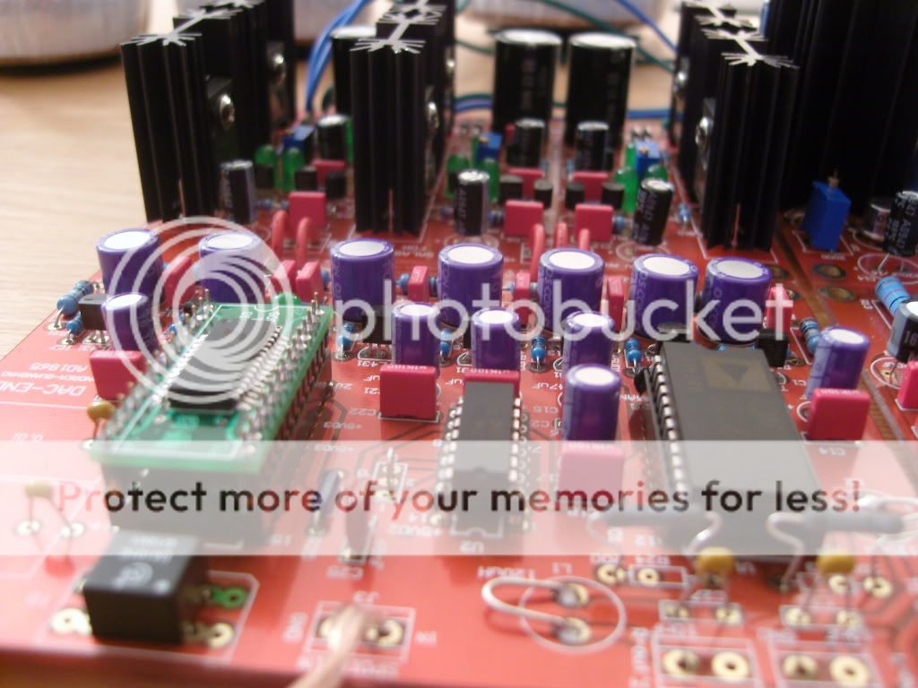
I have fixed the noise. By connecting the middle earth point on the I/V board to "true" earth. Now it sounds perfect.
I used very cheap output cap, not quality at all, but now i have it working i can go ahead and change the parts i skimped on for better ones.
if you use parallel Cap out out: one Cap 0.1uf and one Cap 1uf, the sound is better many many!
if you use parallel Cap out out: one Cap 0.1uf and one Cap 1uf, the sound is better many many!
You are talking about C2 and C6 on the I/V board yes?
So use both 0.1uf parallel with 1uf?
I currently have a cheap 1uf, which i will be changing soon to a better 1uf.
Also i have found the 5687 to be very microphonic. When i even so much as tap the board it resonates right through.
I'm very happy with it, now for the led mod of adamus'.
Thanks agithegreat for sharing your pictures and congratulation for your successful build. Looks like were using the same heatsink, what a coincidence. Where did you buy your 5678 and tube sockets?
I'm way far behind completion. Still waiting for my DAC chip and Mosfets.
Looks like were using the same heatsink, what a coincidence. Where did you buy your 5678 and tube sockets?I'm way far behind completion. Still waiting for my DAC chip and Mosfets.
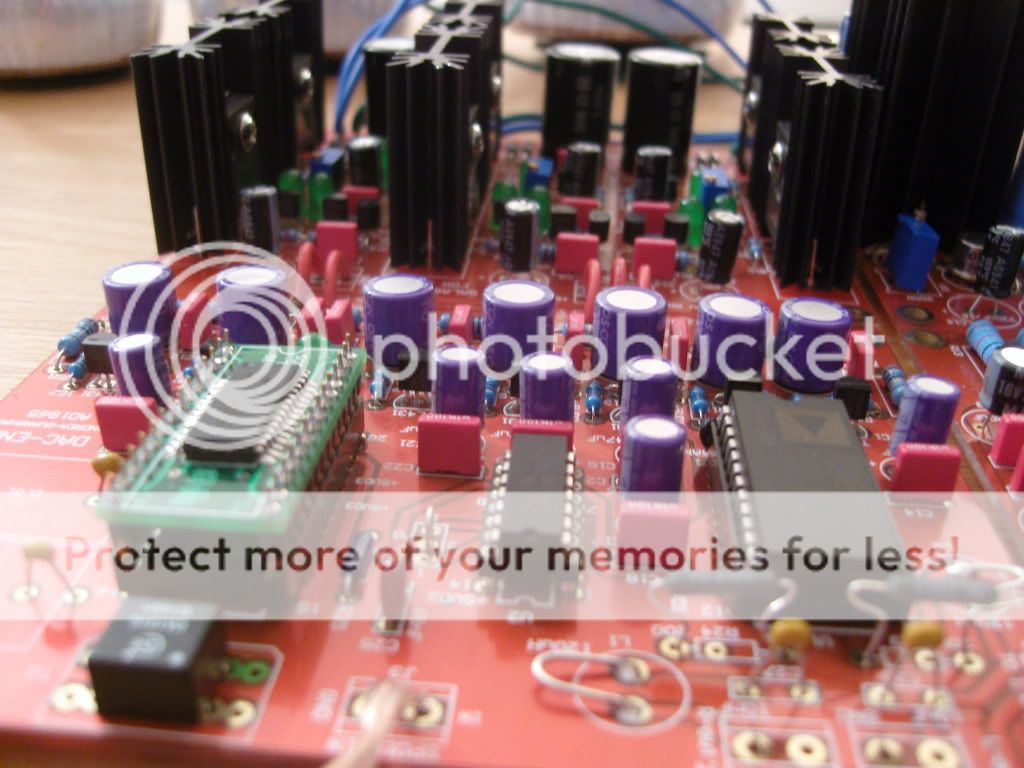
DAC End2 board question
@quanghao, audiodesign
Out of pure curiosity I have a question regarding some connections on the DAC-End2 board:
According to the CS8414 data-sheet, it has M0, M1, M2, M3 as Serial Port Mode Select pins (PINS 23, 24, 18, 17). So one selects the format of the serial output from the receiver, which in our case is LSBJ, thus M3-M0 should be 0110.
Also CS8414 has an analog part for Clock&Data Recovery which has its own analog +5V and analog ground (pins 22 and 21). In order to obtain a low jitter this analog +5V must be of low noise and its ground kept clean.
That's OK...
It's strange to me why the 22 and 24 pins of CS8414 are connected together ? and on the other-hand pin 18 is connected by itself to one +5V (VD4). I saw in earlier schematics of audiodesign that he connected together 22 and 24 and I'm curious why?
Wouldn't be better to connect 24 with 18 to the digital +5V of the CS8414, so VD4 part not needed?
Thank you,
Zsolt
@quanghao, audiodesign
Out of pure curiosity I have a question regarding some connections on the DAC-End2 board:
According to the CS8414 data-sheet, it has M0, M1, M2, M3 as Serial Port Mode Select pins (PINS 23, 24, 18, 17). So one selects the format of the serial output from the receiver, which in our case is LSBJ, thus M3-M0 should be 0110.
Also CS8414 has an analog part for Clock&Data Recovery which has its own analog +5V and analog ground (pins 22 and 21). In order to obtain a low jitter this analog +5V must be of low noise and its ground kept clean.
That's OK...
It's strange to me why the 22 and 24 pins of CS8414 are connected together
? and on the other-hand pin 18 is connected by itself to one +5V (VD4). I saw in earlier schematics of audiodesign that he connected together 22 and 24 and I'm curious why?Wouldn't be better to connect 24 with 18 to the digital +5V of the CS8414, so VD4 part not needed?
Thank you,
Zsolt
agithegreat - the snubber caps on the diodes of the HV supply (blue boxes). - what voltage rating are they?
The blue caps, they are 0.1uf but 630v, as i was unsure on the 450's with 300vac.
Why do you ask?
Thanks agithegreat for sharing your pictures and congratulation for your successful build.
I'm way far behind completion. Still waiting for my DAC chip and Mosfets.
Thanks,
I got nearly everything from farnell. Some things i couldn't find on there, which then i got off ebay.
Except the transformers, which are from antek.
Hi,
Did you get the heatsinks for IRFPs from farnell as well? Mind sharing the code?
Thanks,
F.
I got nearly everything from farnell.
Did you get the heatsinks for IRFPs from farnell as well? Mind sharing the code?
Thanks,
F.
- Status
- This old topic is closed. If you want to reopen this topic, contact a moderator using the "Report Post" button.
- Home
- More Vendors...
- Quanghao Audio Design
- OLD THREAD DAC End by Andrea Ciuffoli