Looking good! What's the size of your bottom plate?
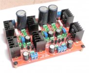
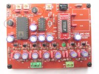
one PC of DAC size: 9.5 x 12.5 cm
All PCb size: 19 x 25 cm
and chassic size: 43 x 32 cm!
Good job, looking for assembling mine.
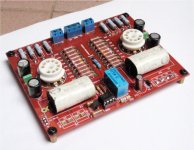
Quanghao, the AD1865 external I/V is done with 2.2K parallel only? I can't see the Caddok 200R on the board.
Caddok 200R:
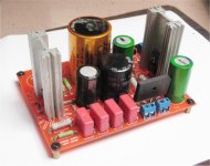
I do not find the small resistor. should find a very large resistance ( 20W)! I put it at the bottom of printed circuit boards! tomorrow I will send you to see pictures!
Hi Quanghao,
my boards arrived today in top condition. Sent on 01/29 arrived 02/04 what is
incredibele fast. Really great job.
Thanks a lot to all who helps to realize this project.
Michael
my board hasn't arrived.... still waiting for it
Hi quanghao,
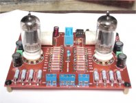
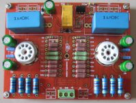
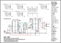
1.do i need to use the L1 and L2 on DAC-end PCB board, is it 120uH inductor?
2.what is the actual value for c26 and c27, is 10nF or 2.2nF?
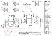
3.which schematic should we follow to build DAC-end?
Thanks
1.do i need to use the L1 and L2 on DAC-end PCB board, is it 120uH inductor?
2.what is the actual value for c26 and c27, is 10nF or 2.2nF?
3.which schematic should we follow to build DAC-end?
Thanks
Attachments
Last edited:
Hi quanghao,
1.do i need to use the L1 and L2 on DAC-end PCB board, is it 120uH inductor?
2.what is the actual value for c26 and c27, is 10nF or 2.2nF?
3.which schematic should we follow to build DAC-end?
Thanks
Hi Sugden ! Im sorry!
When DAc out put wiht tranformer do not use L1, L 2= 120uH and C26, C27= 0.01uF. that is filter
Im sorry,!
thank you!
Last edited:
Where can I buy a real, working CS8414? I bought 4 pieces from chinese seller, 1 was ok, 3 don't work. Please recommend me a reliable seller, who ships worldwide!
From where did you buy, in order to avoid him?

I bought from tube_buyer but did not recieve them yet to tell.
- Status
- This old topic is closed. If you want to reopen this topic, contact a moderator using the "Report Post" button.
- Home
- More Vendors...
- Quanghao Audio Design
- OLD THREAD DAC End by Andrea Ciuffoli