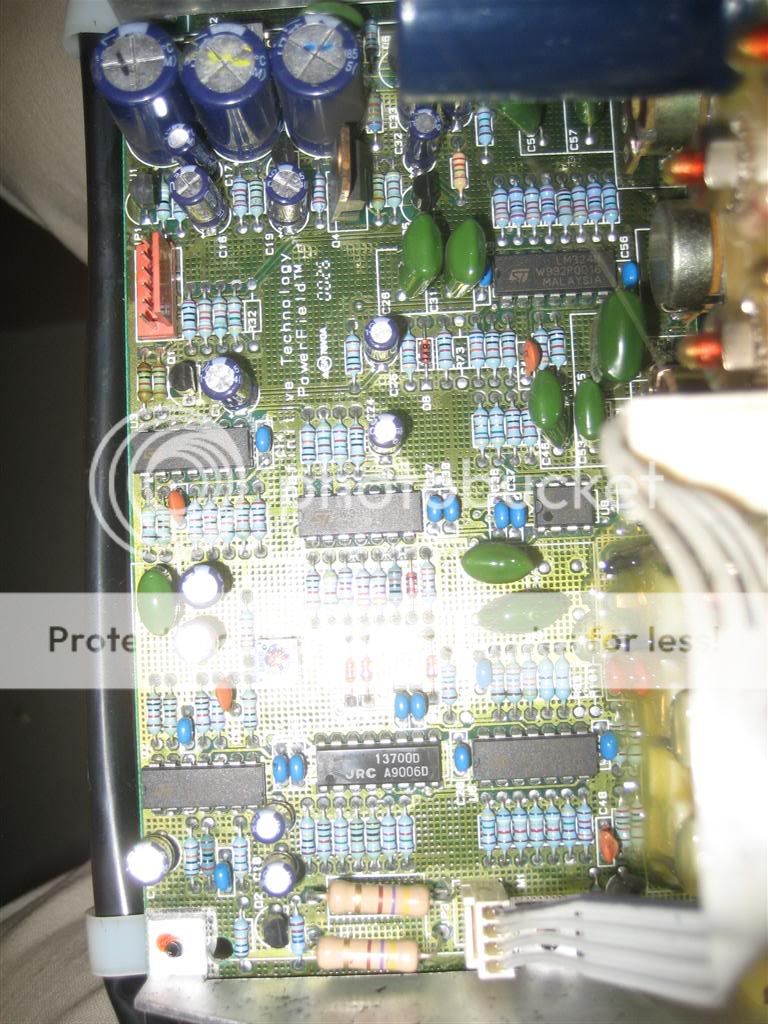
I just bought a broken Definitive Technology PF15TL subwoofer from a guy for cheap... nice big 15"er with what is claimed to be a 325w amplifier. But, looking inside is a single STK4050V chip??
The guy said it just stopped working one day, but the power LED still comes on. Which I confirmed, light comes on, it makes a little noise shortly after powering, but no output from signal.
So, probably means the chip is blown? Not a big deal, can be replaced and all the resistors look OK, so probably not a hard fix?
But, this chip is only rated for 200wRMS at 8ohms, yet they claim 325w, plus the woofer measures 3.9ohms. I'm guessing the amp may put out around 300 some watts at 4 ohms, but is that a safe load for it? Also, it appears to use a Silpad but there's also some thermal grease used between both the chip and pad and pad and heatsink... I thought you weren't supposed to use grease with those pads?
Did this company do something special with this chip to get 325w and be able to drive a 4 ohm woofer? Could that or something else affected the longetivity and cause this thing to blow? It's about 5-6 years old, but for an originally $700 speaker, that's not too good.
I don't have a schematic let alone any specs on the subwoofer, couldn't really find anything online.
I did some testing and I'm not sure the chip is blown. No pins were shorted at all and the "diode test" results seem to be consistent with the equivalent circuit in the datasheet. I did find a blown 1/2 watt metal film resistor which I think is 19.1k ohms that connected to pin 4 and then to the collector of an MPSA92.
Someone at Definitive has said they can give me some information about the amp, which I'm hoping includes a schematic, so that should help.
I've attached a picture with the pin voltage readings I measured with a copy of the equivalent circuit pasted in as well, if anyone is interested at looking at it. To clarify, the two lines at the bottom with '0' meant no reading, all pin combinations not shown had same reading. All readings taken from chip out of circuit.
Attachments
pin 4
Looks to me like pin4 is usd to bias the front end of the amp. If the transistor that 'supplies' this pin is blown, I'd expect the amp to be silent...
Without more info it's difficult to diagnose with any accuracy, but fixing the transistor and it's associated components may take care of the problem...
regarding the power rating...they are perhaps using some short term power delivery specification, not continuous RMS watts. The size of the transformer and heatsink will give a better indication of it's long term capabilities...
HTH
Stuart
Slightly off topic
I have Q & A for the sub woofer amp builders:
Situation: a stereo pre-amp, how do I connect these outputs and "combine" them for the third single channel to drive an active sub ??
(I have a bottlehead tube pre-amp kit coming and I want to output to the two main amps (stereo) and also to my sub woofer (a power MOSFET single channel amp.)
A simple resistive summing network will sum the left and right channel signals. It will also attenuate them, so some extra gain will be required in the sub amp to normalize the levels.
Make a Y with three resistors. Use 3 10kohms for example. Ground the lower terminal of the Y and connect each source channel to an upper terminal of the Y. The summed signal is at the center of the Y, and in the case of 3 10kohm resistors, each channel's voltage level is reduced by a factor of 3.
Make a Y with three resistors. Use 3 10kohms for example. Ground the lower terminal of the Y and connect each source channel to an upper terminal of the Y. The summed signal is at the center of the Y, and in the case of 3 10kohm resistors, each channel's voltage level is reduced by a factor of 3.
Re: pin 4
The resistor was the only defective component I found. Still not sure if the chip itself is bad, but it seems it may be okay. I'm hopeful that replacing the resistor would fix the amp, but I still have more components to test and I'm waiting on a schematic before I attempt to fix and test.
As for the heatsink and transformer, the chip is mounted to a 4mm thick, 406mm x 178mm plate with a 122x102mm heatsink with 3mm base, and 13 17mm high fins mounted on the outside of the plate behind the chip. The transformer is 105X115X92mm and pretty heavy.
Stuart Easson said:Looks to me like pin4 is usd to bias the front end of the amp. If the transistor that 'supplies' this pin is blown, I'd expect the amp to be silent...
Without more info it's difficult to diagnose with any accuracy, but fixing the transistor and it's associated components may take care of the problem...
regarding the power rating...they are perhaps using some short term power delivery specification, not continuous RMS watts. The size of the transformer and heatsink will give a better indication of it's long term capabilities...
HTH
Stuart
The resistor was the only defective component I found. Still not sure if the chip itself is bad, but it seems it may be okay. I'm hopeful that replacing the resistor would fix the amp, but I still have more components to test and I'm waiting on a schematic before I attempt to fix and test.
As for the heatsink and transformer, the chip is mounted to a 4mm thick, 406mm x 178mm plate with a 122x102mm heatsink with 3mm base, and 13 17mm high fins mounted on the outside of the plate behind the chip. The transformer is 105X115X92mm and pretty heavy.
" ... Make a Y with three resistors. Use 3 10kohms for example. Ground the lower terminal of the Y and connect each source channel to an upper terminal of the Y. The summed signal is at the center of the Y, and in the case of 3 10kohm resistors, each channel's voltage level is reduced by a factor of 3. ..."
I knew about this, but wanted something that more closely match common practice in the tube world = hoping to reduce cross talk between the stereo channels as much as possible. I would have used 100K rather than 10K and then paralleled 50K trim pots to get gain and balance under control.
Is there an interesting op-amp solution, like a summing op-amp with input impedence >> 1 meg? (ala my avatar image the AD825) ... that way I could use a low pass active filter / crossover as a part of the circuit. I suppose I should just dust off the ol' op-amp cookbooks and roll my own. I was just hoping for the latest DIY wisdom here.
sounds big enough to me...
Definitive rate all their current subwoofers in RMS watts, so I'd assume this one is rated the same way...and they have increased the rating on the PT15TL+ model to 500w RMS...
The transformer and heatsink sound pretty beefy, not sure if they can do 350w RMS continuously or not, but given the very +ve reaction people seem have to Definitives subs it sounds more than adequate...
Anyway the rails used to drive this amp have to be at least +/-72v to get 325w RMS, probably with 20% more to allow for component tolerances, transformer regulation, mains dips etc. Please be careful, there's more than enough energy to hurt you.
Here's a WAG: if muting is implemented by a 19.1k resistor used from pin4 to ground (or worse +ve), with the mpsa92 stealing current to -ve, the 1/2w resistor is close to it's rating with ~85v rails (to +ve would exceed it's power rating). If it is also an overload or protection mechanism, the resistor could be subject to high temps if the mute/protect is on too long...did the previous owner like to play it loud?
HTH
Stuart
Re: sounds big enough to me...
Would a higher rated resistor be better? Not sure if that exact of a value is available in higher wattages, though
I didn't ask the owner how hard he liked to play it, but it's probably a good bet he had it loud when he used it. Could the resistor acted in a protective manner by burning out due to high clipping and left the amp chip intact along with everything else?
Hope to have a schematic soon, which I'm sure would be more helpful in diagnosing the problem. I'll see if I can trace down the circuit a bit more, it's just difficult since it's a double-sided board.
Stuart Easson said:Definitive rate all their current subwoofers in RMS watts, so I'd assume this one is rated the same way...and they have increased the rating on the PT15TL+ model to 500w RMS...
The transformer and heatsink sound pretty beefy, not sure if they can do 350w RMS continuously or not, but given the very +ve reaction people seem have to Definitives subs it sounds more than adequate...
Anyway the rails used to drive this amp have to be at least +/-72v to get 325w RMS, probably with 20% more to allow for component tolerances, transformer regulation, mains dips etc. Please be careful, there's more than enough energy to hurt you.
Here's a WAG: if muting is implemented by a 19.1k resistor used from pin4 to ground (or worse +ve), with the mpsa92 stealing current to -ve, the 1/2w resistor is close to it's rating with ~85v rails (to +ve would exceed it's power rating). If it is also an overload or protection mechanism, the resistor could be subject to high temps if the mute/protect is on too long...did the previous owner like to play it loud?
HTH
Stuart
Would a higher rated resistor be better? Not sure if that exact of a value is available in higher wattages, though
I didn't ask the owner how hard he liked to play it, but it's probably a good bet he had it loud when he used it. Could the resistor acted in a protective manner by burning out due to high clipping and left the amp chip intact along with everything else?
Hope to have a schematic soon, which I'm sure would be more helpful in diagnosing the problem. I'll see if I can trace down the circuit a bit more, it's just difficult since it's a double-sided board.
bigger resistor
Bearing in mind I am guessing about whats going on here:
The use of a bigger resistor would be an excellent idea, I'd use something more like 2W or 5W if the connection point is to +ve instead of ground.
The app note for the chip shows a 10k resistor to ground, perhaps Definitive doubled the value to make the +ve connection safer...anyway you can always use a pair of 9 or 10k resistors to get more power handling at the value you need, I'm pretty certain this value isn't critical.
Let us know what they send you, I'd be very interested in how they hook it all together...
Stuart
Well, you were right about the resistor. After spending a few hours going over the board with a multimeter and not finding anything strange followed by lots of thinking, I took a few resistors, strung them together to get around 18-20K, put them in and put it all back together and plugged it in. It worked!
I would have hooked up my ammeter to it and used my variac to see if it was going to draw heavy current, but considering it turned on previously with no bad effect and finding nothing but a burnt resistor and everything else OK, I decided to take a risk. Fortunately, it worked out.
I'm still waiting on Definitive to send me any information, hopefully technical, on the subwoofer, which I'll be happy to share. It'd be nice to have for the future, just in case.
I still have to replace my make-shift "resistor array" with a single multi-watt piece, but I'm glad to know this was one of the easiest amp fixes I've ever had.
well that was easy...
congratulations, it's so nice to get an easy fix every once in a while.
Do you notice the resistor getting hot in normal use or under muting conditions?
My most recent easy 'fix' was to replace fuses in a 'dead' Sony receiver, the previous owner had replaced it before he asked if I wanted to take a look at it...oh well, now I have a nice home theater receiver.
Stuart
The Definitive guy got back to me. He sent a schematic. The resistor that blew was R89, which is on page 5.
He also told me they don't fix these amps, they just replace the entire board... which is $225! That's about 3x what I paid the guy for whole thing, lol
He also told me they don't fix these amps, they just replace the entire board... which is $225!
That's about 3x what I paid the guy for whole thing, lol Attachments
Very interesting...
A note in the schematics mentions a reduction in the idle current at mute...not sure if it matters, since it looks like the resistor in question is most stressed under normal operation...
A couple of things are clear from these diagrams...
Assuming your model has the same voltage rails listed on the schematic, the 19.1k resistor sees 24+66v under normal operating conditions, which gives 0.42w dissipation, a little close to the 0.5w rating for my taste. Inserting a 5w resistor would probably be overkill...1 or 2w should have a long and useful life...
The schematic 'claims' a rating of 250w into 4 ohms, presumably with 66v rails, but then claimes the limiter is set to give a peak of 360w into 4ohms (180w RMS). There is a little comment that suggests there are other versions with different power ratings, perhaps there is some mixing of settings here...
Have fun with your new toy, I'm assuming it is loud enough...;^)
Stuart
hi everyone- I know this thread is really old, I found it via a google search. I recently bought a Definitive Tech PF15TL+ and it is in mint condition. It worked great for about a week or so (never had the level above 40% or so, and the guy who had it before me was careful with it as well) but then today it suddenly stopped working. The amp power LED is still on, and it makes a tiny pop when the auto power-on kicks in, but zero output.
Sounds like the exact same problem the original poster stated...
Now..Im not an EE by any means, if I took the amp apart Id understand that Im looking at a bunch of resistors, FET's, and what have you...but I have no idea how they actually work together to make an amplifier. Anyway, I have no idea where to start with diagnosis.
Anyone have any ideas that might be able to help me out? I have a multimeter and can solder anything, but I just dont know where to start checking... ie any advice like "ohm resister so-and-so and if its below X ohms its dead, solder in a new one", etc...
thanks for the help!
ben
Here is the only thing that might be wrong?? I dont know if those two resistors are supposed to be that color, they look a little brown???
should I pull the actual amp and transformer out of the sub box? As long as its unplugged its "safe" right? I dont know if any of those capacitors hold a nasty charge even when unplugged like CRT tv's do...
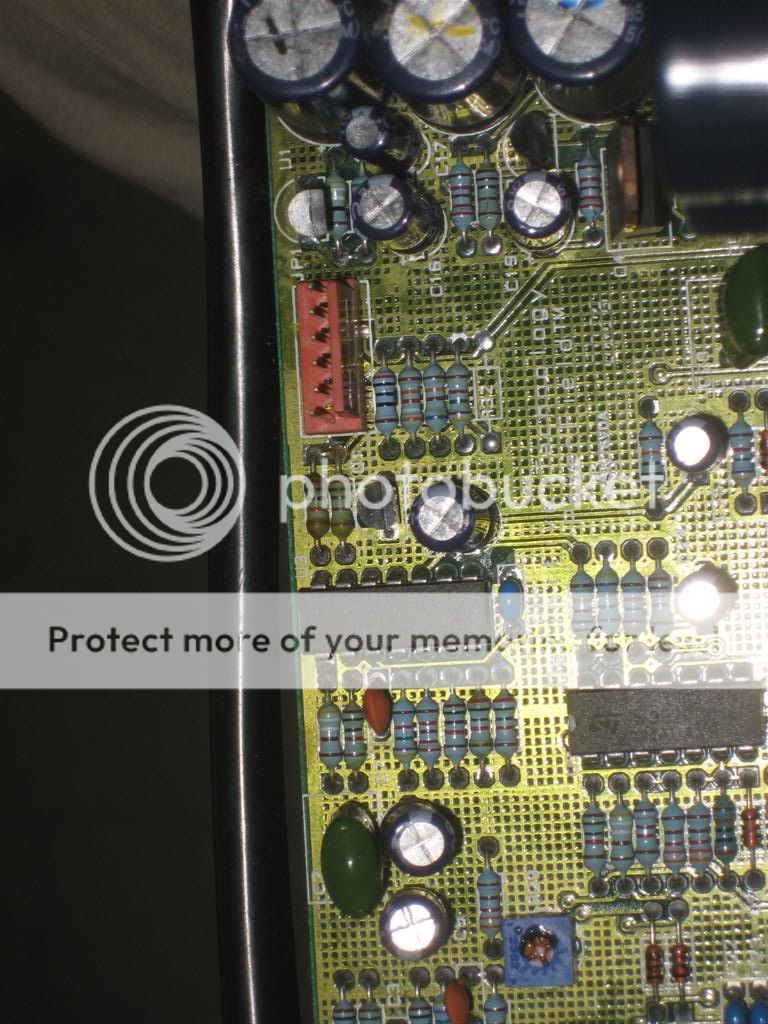
should I pull the actual amp and transformer out of the sub box? As long as its unplugged its "safe" right? I dont know if any of those capacitors hold a nasty charge even when unplugged like CRT tv's do...
- Status
- This old topic is closed. If you want to reopen this topic, contact a moderator using the "Report Post" button.
- Home
- Amplifiers
- Chip Amps
- STK4050V and it's use in Definitive Tech PF15TL subwoofer