Hi There
I'm interested in making an amp with ultimate performance. Best possible efficiency is not needed, but my proposal uses a digital part at high frequency, so I hope I'm right in this thread.
My idea is to use an analog (Class A or AB) amp and build around this amp a digital correction network. The analog amp does most of the power and the digital correction makes the quality like a booster.
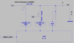
The analog amp must be a "transconductance amplifier" and on the ouput node a correction current is added or subtracted from. If the transconductance amplifier makes around 50W (+- 5A @ 4Ohm) and has a THD of better 60dB, then for the correction current only +-5mA is needed. The correction can now boost the quality up to 120dB or more.
Control of the correction does a DSP. The DSP can learn at low speed the delay of the transconductance amplifier and also the gain matching of the measured output value. It calculates the correction value which is output at a high speed current DAC (8*fs).
Advantage:
transconductance amplifier has:
- very high PSRR
- independant of speaker impedance
- good control of moving coil (remember: F=IlxB)
digital correction is done in the PCM regime (no PWM needed)
A/D and DAC's are available up to 24bit 8*fs
Disadvantage:
low efficiency
transconductance amplifier is not very common (Nelson Pass is making a lot)
For simplicity a unipolar transconductance amplifier is shown which needs an output cap.
Comments are welcome.
Thanks Emil
I'm interested in making an amp with ultimate performance. Best possible efficiency is not needed, but my proposal uses a digital part at high frequency, so I hope I'm right in this thread.
My idea is to use an analog (Class A or AB) amp and build around this amp a digital correction network. The analog amp does most of the power and the digital correction makes the quality like a booster.
The analog amp must be a "transconductance amplifier" and on the ouput node a correction current is added or subtracted from. If the transconductance amplifier makes around 50W (+- 5A @ 4Ohm) and has a THD of better 60dB, then for the correction current only +-5mA is needed. The correction can now boost the quality up to 120dB or more.
Control of the correction does a DSP. The DSP can learn at low speed the delay of the transconductance amplifier and also the gain matching of the measured output value. It calculates the correction value which is output at a high speed current DAC (8*fs).
Advantage:
transconductance amplifier has:
- very high PSRR
- independant of speaker impedance
- good control of moving coil (remember: F=IlxB)
digital correction is done in the PCM regime (no PWM needed)
A/D and DAC's are available up to 24bit 8*fs
Disadvantage:
low efficiency
transconductance amplifier is not very common (Nelson Pass is making a lot)
For simplicity a unipolar transconductance amplifier is shown which needs an output cap.
Comments are welcome.
Thanks Emil
Attachments
...somehow the idea is nice. But you are ignoring some basics.
If you use a real transconductance amplifier like in your schematic, then every impedance nonlinearity + back EMF of your speaker and X-over will be reflected as a voltage error at the amp output. Your digital correction is regulating for proper output voltage. With real speaker behaviours you will have to correct in the range of several amps, not just mA.
If your transconductance amp is not a real transconductance amp but with voltage sensing feedback in order to provide a low driving impedance... then your correction will have to fight against the main amplifier.
If you want to make the entire amplifier including correction circuit act like a transconductance amp, then your correction circuit must sense the speaker current, not the voltage. ...then your idea could work in principle.
But please note: Most speakers are designed for voltage drive, not for current drive. With current drive most speakers will sound quite different from what the designer had intended. That's why transconductance amps are not so common.
Hi ChocoHolic,
Thanks for your well-founded response.
I don't know if BQDC does work?
The smart thing is, that a lot of cheap DACs up to 24bit or several MHz (super oversampling) are availabe. No sub ns-switching and only some mA instead of several Ampere; and this all in PCM.
Thanks for your well-founded response.
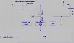
you are right! the current must be sensed. The GND return path can be used for the current sensing.If you want to make the entire amplifier including correction circuit act like a transconductance amp, then your correction circuit must sense the speaker current, not the voltage. ...then your idea could work in principle.
There are a lot of simple designs where the constant current source of a transconductance amp is made with a FET with more than several MOhm. Of course voltage feedback with this amp is not allowed, only current feedback or no feedback.If your transconductance amp is not a real transconductance amp but with voltage sensing feedback in order to provide a low driving impedance... then your correction will have to fight against the main amplifier.
I don't think that you can design a speaker only for voltage drive. Every speaker can be used with both. Current drive gives a different (maybe better?) acoustical response, but anyway the X-over has to be done correctly. Nelson Pass shows excellent results with current drive.Most speakers are designed for voltage drive, not for current drive. With current drive most speakers will sound quite different from what the designer had intended. That's why transconductance amps are not so common
I don't know if BQDC does work?
The smart thing is, that a lot of cheap DACs up to 24bit or several MHz (super oversampling) are availabe. No sub ns-switching and only some mA instead of several Ampere; and this all in PCM.
Attachments
Of course every speaker cone will move, no matter if you use current drive or voltage drive.
But the relation between current and cone movement is quite different.
Most obvious point is the damping. With current drive the overal damping will equal to Qm, because you do not get any electrical damping effect.
So if you run your speaker through the resonance most speakers will show quite some overshoot in the frequency response. And usually most designs have the resonance frequency of the woofer in the area of normal bass music. You will also see this if you measure the voltage across the speaker. With current drive the voltage in the range of the resonance frequency is by far higher than at other frequencies.
If you drive it by voltage then the voltage across the speaker is constant for all frequencies, and in turn due to the high impedance at the resonance frequency you will have quite small currents in the speaker....
Also the design of the X-over for a current drive system might be optimized in a different way from a voltage driven system.
There are speaker systems which work fine with current drive. May be you can search for this topic in the forum, I am quite sure you will find a lot hints, which speaker systems do perform well with current drive.
To get your idea running.... I am afraid, I am not the right one. Digital is not my strentgh.
- Status
- This old topic is closed. If you want to reopen this topic, contact a moderator using the "Report Post" button.