With every amplifier i repair, i learn new things. this Classe DR-15 i have been working on is the first really high end amplifer i have had an opportunity to get my hands into. I have repaired literally hundreds of PA, Bass and mid level home amplifiers but very few amplifiers of what i would consider to be of any audiphile type quality. Simple because i typically cannot afford to buy them even when broken!
Now that i have the defective channel repaired. i need to get it properly set up. The service Notes list how to set the offset adjustment but dont give too many details as to the details of this proceedure.
My service notes say to first test the channel with a signal generator to make sure you get a wave form. it then says to turn the signal off and
turn the Bias trimpot to minimum and adjust offset for less then 5mv of offset.
Now this seems simple enough, but should i have a load resistor connected at this time? it doesnt state one way or the other. it may not make a difference. the service notes dont mention a load resistor until much later during the square wave test's so i am assuming i do not need one.
I lowered bias to zero and observed that the offset was zero. I then reset bias to the 20mv level specified. I noticed that the ofset was then around 18mv or so. I dont know if that is acceptable or not. Normally i would not even be concerned about that low of an offset. But i figured i would ask.
I want to do everything i can to make sure this repair is done to the best of my abilities.
Zc
Some class AB amps as you have discovered have both a bias and an offset ajustment. Let's assume a simple push-pull output, no load, no input.
Put a voltmeter between the two base's of the output drivers. Bias will vary this from nearly 0 to slightly greater than 1.2. You want the transistors to conduct slightly and thus you nned a little more than 0.6V on each output to do so.
If you look at the topology of the amp, there are better locations to monitor the bias adjustment for start-up. This generally isn't the place to adjust it though.
Most manuals will tell you to measure the voltage across the emitter resistors. In either case your setting the quiesent current through the drivers. If it is set too high the AC mains current will be significantly high and thermal run-away will happen easily. To low and you'll have cross-over distortion. The best method for setting the bias is a distortion anayzer, but without that or a service manual <50 mV and probably more like 10 or 20 mV across the emitter resistor. Keep an eye on the output transitor heat sink temperature at no load for an hour or so.
So that's how I set and check if the bias system is working properly.
When you bring up the amp from just being serviced, use a signal generaor and monitor for clipping and try to keep the voltage between the bases at minimum by modifying the bias ajustment.
Offset adjustments generally exists in lower quality amplifiers. It always makes sense to check it. Some service manuals say below 100 mV is OK. The closer to zero, the better.
KISS said:Put a voltmeter between the two base's of the output drivers. Bias will vary this from nearly 0 to slightly greater than 1.2. You want the transistors to conduct slightly and thus you nned a little more than 0.6V on each output to do so.
If you look at the topology of the amp, there are better locations to monitor the bias adjustment for start-up. This generally isn't the place to adjust it though.
This is not the place to measure it, period. Bias current is exponentially related to Vbe. A few millivolts up or down may mean hundreds of mA.
I meant to post the schematic earlier.
I was checking for offset at the speaker output.
Here is the schematic:
and her is a link to the PDF of the schematic and the end of the PDF list's all the service notes.
http://www.audio-circuit.dk/Schematics/CLASSE_DR-15-TM.pdf
I was checking for offset at the speaker output.
Here is the schematic:
An externally hosted image should be here but it was not working when we last tested it.
and her is a link to the PDF of the schematic and the end of the PDF list's all the service notes.
http://www.audio-circuit.dk/Schematics/CLASSE_DR-15-TM.pdf
That's what I said. Between the bases is a VERY GOOD place to start, not where to measure the BIAS current. You'll get a much quicker INDICATION as to whether the bias regulator is working when you look at it here. The voltage across the emitter resistors won't change for a large adjustment (# of turns) especially if you use 10-turn pots like I do.
You can have 0V across the emitter resistors, but the voltage between the bases will be varying, then SUDDENLY the voltage across the emitter resistors indicate a measureable current.
Based on that info, wouln't you look there first to make sure the bias regulator is functioning properly before you set it?
There will be some amount of interaction. What's vary important is the variation of bias adjustment on each transistor. If they are drastically different then one transistor hogs a little more of the current and takes all the "wear and tear". The emitter resistors help smoothe that out.
The only other way to smoothe the variation out is to "match" the hfe of the output transitors with a transistor checker. Match the hfe's of the NPN's and the hfe's of the PNP's.
Bias and offset don't require a load.
You can always tweek the adustments, but in all likelyness the potentiometers may not allow such a fine control. It also goes without saying that <5 mV means -5 mV < 0 < +5 mV. Offset is usually measured at the speaker terminals.
Thanks,
The transistors are factory matched parts so i used them as is. and i was amazed at how much fine control the BIAS pot gave me. i mean i could really dial that bias in. each half turn didnt vary the bias much and it took a lot of half turns to go from .35mv across the Emitter resistors to .001mv
Should i be setting offset cold? How about Bias? or should i set rough bias and let the amp warm to operating temp then set final bias?
Zc
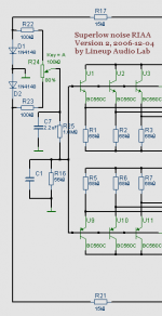
Offset compensation and Adjust
Zero Cool.
In my attachment you see how I did this in one of My amplifiers.
It is the components in upper left.
The potentiometer adjusts, how much current, positive or negative
that is provided by R25, 1 MOhm.
By using such high resistor, we do not effect Input Impedance, too much.
Another way, using current sources for active bias compensation
is to be found in this lineup topic.
Including diagrams.
Offset Correction using Bias Compensation
---------------------------------------
In your amplifier I would try the more simple method
or something like it.
Like is shown in my Attachment.
Regards
lineup
Zero Cool said:Thanks,
Should i be setting offset cold? How about Bias? or should i set rough bias and let the amp warm to operating temp then set final bias?
Zc
Zero Cool.
In my attachment you see how I did this in one of My amplifiers.
It is the components in upper left.
The potentiometer adjusts, how much current, positive or negative
that is provided by R25, 1 MOhm.
By using such high resistor, we do not effect Input Impedance, too much.
Another way, using current sources for active bias compensation
is to be found in this lineup topic.
Including diagrams.
Offset Correction using Bias Compensation
---------------------------------------
In your amplifier I would try the more simple method
or something like it.
Like is shown in my Attachment.
Regards
lineup
Attachments
Re: Offset compensation and Adjust
I dont really have a choice. this is a Classe amplifier i am repairing. not a new design.
Zc
lineup said:
In your amplifier I would try the more simple method
or something like it.
Like is shown in my Attachment.
Regards
lineup
I dont really have a choice. this is a Classe amplifier i am repairing. not a new design.
Zc
Hi,
you do the set up @ operating temperature.
However, it is worth checking what happens to both output offset and Iq as the temperature changes from start up to final operating temperature.
As an example, you may find that offset varies from 30mV cold to -20mV warm. You can move the warm setting to 0mV but the cold value will increase to about 50mV. A good compromise might be 40mV cold to -10mV warm and most of the time during warm up it is in the range +-10mV. This setting will vary a little with the seasons (even in centrally heated homes the summer temps exceed the winter temps).
- Status
- This old topic is closed. If you want to reopen this topic, contact a moderator using the "Report Post" button.
- Home
- Amplifiers
- Solid State
- Setting Offset - Proper setup