I've been working on my LM3886 chipamp for quite some time now. A few months back, it was up and running. Satisfied with the function of the amp, with little DC offset, I finished soldering all the connections, fastened the toroid and power supply board to the enclosure, and put the top and bottom on (perforated steel). I left for a few months on a research trip and I came back. Now...
My fuse blows when I turn on the amp. I've upped the durability of the fuses - I'm up to 3 amp slow-blow. I switch it on (through a power strip), the LED lights up, I hear an audible humming sound from the amp (no speakers), and it clicks off. With the slow-blow it takes slightly longer, but I'm not sure where the problem is. Any ideas? I have very little electronics knowledge. This has been a big learning curve, and I have managed to not blow myself up yet. I am at the mercy of your help.
I have a long weekend coming up, so it would be nice to finish it up.
Thanks,
Alex
You can follow my progress in these threads.
http://www.diyaudio.com/forums/showthread.php?s=&threadid=74843
http://www.diyaudio.com/forums/showthread.php?s=&threadid=60665
http://www.diyaudio.com/forums/showthread.php?s=&threadid=59448
http://www.diyaudio.com/forums/showthread.php?s=&threadid=59507
http://www.diyaudio.com/forums/showthread.php?s=&threadid=58594
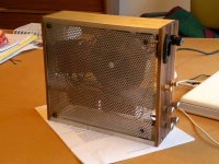
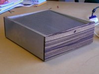

Thank you for the nice comment. It's really a pretty functional enclosure - it's the zebra wood that does the trick.
As for the short, the part I don't understand is that it worked fine before. I suppose when I screwed down the standoffs to the bottom piece, it could have created a short. But, the standoffs are insulated on the board from the circuit. The grounding wires off the two amp boards and the ac plug are simply twisted together and surrounded with electrical tape. Not an elegant solution, but I don't think that would cause a short.
As for the short, the part I don't understand is that it worked fine before. I suppose when I screwed down the standoffs to the bottom piece, it could have created a short. But, the standoffs are insulated on the board from the circuit. The grounding wires off the two amp boards and the ac plug are simply twisted together and surrounded with electrical tape. Not an elegant solution, but I don't think that would cause a short.
Attachments
The transformer humming indicates a short. Verify your transformer to PSU wiring. Try powering up just the transformer.
Check with an ohmmeter that your PSU input is not a short. Check each diode in the bridges. Be sure that you haven't bumped the diodes so that one is touching a neighbor. Try powering up just the PSU without the amps connected.
Could you have reversed the polarity of the PSU to amp connections? I know this is unlikely, but worth a look.
Connect one channel at a time to the PSU - after the caps have bled down.
Good luck.
Are there any sharp edges that could have cut the PSU leads as they run under the heat sink? How do the leads get from one side to the other?
Safety note - put some heat shrink over the mains connection terminals. I bought some 1" stuff to put over the fuse holders. Yes, I know it is there and I could avoid it but I "grew up" with tubes and got shocked enough that I am cautious.
Safety note - put some heat shrink over the mains connection terminals. I bought some 1" stuff to put over the fuse holders. Yes, I know it is there and I could avoid it but I "grew up" with tubes and got shocked enough that I am cautious.
Everyone's always so helpful, thanks.
I verified all the original wiring, the integrity of the cable housing, etc. The only change from the functional iteration a few months back - I had switched the amp board to binding post connections, left to right. Shouldn't matter. Otherwise, everything looks fine. No errant touching wires, no loose connections, no soldering problems.
The clearance over the mounting bolt is about a half inch. I understand the toroid can create a magnetic field, which can cause some problems? They certainly aren't touching.
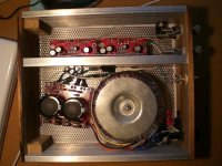
The PSU leads run under the heat sink (the middle aluminum piece) The Heat sink
piece is half inch shorter to allow the through-space on the bottom. There aren't any sharp edges and all the wires seem to be in fine shape. I will get some more heat shrink. The only kind I have at the moment is small gauge, so it won't fit over the connectors. I'll do this before I power it up again. Safety first.
BobEllis said:The transformer humming indicates a short. Verify your transformer to PSU wiring.
I verified all the original wiring, the integrity of the cable housing, etc. The only change from the functional iteration a few months back - I had switched the amp board to binding post connections, left to right. Shouldn't matter. Otherwise, everything looks fine. No errant touching wires, no loose connections, no soldering problems.
Originally posted by ash_dac What's the clearance above the torroidal mounting bolt ? Is the case grounded ?
The clearance over the mounting bolt is about a half inch. I understand the toroid can create a magnetic field, which can cause some problems? They certainly aren't touching.
Originally posted by BobEllis Are there any sharp edges that could have cut the PSU leads as they run under the heat sink? How do the leads get from one side to the other? Safety note - put some heat shrink over the mains connection terminals.
The PSU leads run under the heat sink (the middle aluminum piece) The Heat sink
piece is half inch shorter to allow the through-space on the bottom. There aren't any sharp edges and all the wires seem to be in fine shape. I will get some more heat shrink. The only kind I have at the moment is small gauge, so it won't fit over the connectors. I'll do this before I power it up again. Safety first.
AndrewT said:connect the series mains light bulb and power up through that.
I saw your post about this the other day. "How many times do we have to tell people to install a mains light bulb." I am afraid I don't understand what you mean. Are you referring to the LED in the PSU?
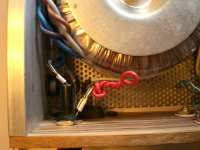
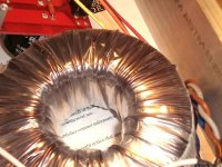
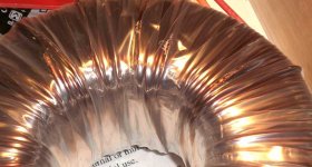
So, with questions answered, that gets me to perhaps the real problem. I checked on everything that people asked about. When I took the enclosure bottom off to check all the connections, I noticed the shrink wrap on the toroid had worn through on several spots. It is as if the wrap had been cut away and the copper winding actually sanded down. I think you should be able to see this in the two photos below. With that, I have two questions:
-What could have caused this? I don't remember sanding down the shrink wrap. There don't really appear to be any burn marks or melted wrap. I assume this is the short.
-What do I do about this?
-What could have caused this? I don't remember sanding down the shrink wrap. There don't really appear to be any burn marks or melted wrap. I assume this is the short.
-What do I do about this?
Attachments
schmalex said:-What could have caused this? I don't remember sanding down the shrink wrap. There don't really appear to be any burn marks or melted wrap. I assume this is the short.
-What do I do about this?
1. Transformers always vibrate. Failing to install the rubber pad that comes with the toroid can cause this type of abrasion.
2. Install the rubber pad. You will also have to repair the exposed copper on the transformer. Electrical tape will work but is somewhat ugly.
I suppose the first time I fired it up (and the fuse blew) I may have had the new cover on top - the perforated sheet. It could have been touching the mounting bolt for the toroid, or at least been close. Could that have caused this?
In either case, I would guess the exposed copper touching the bottom panel, which is connected to the rest of the case, probably causes the short?
Can I ground the case with a wire running from somewhere on the case to the grounding point on the AC socket. Sorry for the loose terminology. I'm pretty sure this is the star ground (the grounding point for the AC socket and the two amp boards).
Attachments
jeff mai said:
1. Transformers always vibrate. Failing to install the rubber pad that comes with the toroid can cause this type of abrasion.
2. Install the rubber pad. You will also have to repair the exposed copper on the transformer. Electrical tape will work but is somewhat ugly.
They vibrate - Interesting. I wish I had know that.
As far as I can recall, the transformer only came with one rubber pad. I will get another. When you say "repair the exposed copper" do you mean simply cover over it, hence the electrical tape?
schmalex said:I suppose the first time I fired it up (and the fuse blew) I may have had the new cover on top - the perforated sheet. It could have been touching the mounting bolt for the toroid, or at least been close. Could that have caused this?
Yes, the vibration from a shorted turn could have caused this abrasion, but it wouldn't have happened with the rubber pad installed.
A shorted turn happens when there is a closed conductive path that passes through the centre hole of the toroid. The mounting bolt should only ever touch the chassis on one end. If it touches on both ends you have formed a shorted turn. Large currents are induced through this path (it's how transformers work.)
schmalex said:When you say "repair the exposed copper" do you mean simply cover over it, hence the electrical tape?
It may involve more than that if any turns are exposed to each other. Perhaps others here can give better recommendations on repair? I'm unsure of what's best from a safety perspective. The damage is to the low voltage secondary windings from your photos, so at least there is no worry about mains voltages.
- Status
- This old topic is closed. If you want to reopen this topic, contact a moderator using the "Report Post" button.
- Home
- Amplifiers
- Chip Amps
- Help with blown Fuses LM3886, Chipamp.com