Hi All,
I'm trying to repair a C-Audio RA2000 amp for a friend of mine. I've had it sat around for months so I can't remember what he told me was wrong, but when I turn it on the 'Protect' LED lights immediately.
I have not tried it with speakers attached yet, but I believe it should only protect itself is the poles are short or have too low impedance...
Does anyone have any schematics and/or advice about fixing this amp. I'm trying to work out what can trigger the protect circuit.
So far I've checked the Rectifiers and other Diodes, and have also gone through all the FETs - As far as I can tell they are all okay (Although the two poles of each rectifier connected across the transformer read short [as expected] and I can't easily take them out to test).
Each channel has a group of four 110v 4700uF caps on their supply (which I believe are for smoothing?), and every one of these caps is bulging at the top. I suspect a need to replace these but I'm not convinced that they're the cause of this exact fault. At approx £10 per cap I don't want to rush into replacing these yet!!!
Any advice, or diagrams, or explanations of the principles surrounding protection circuits will be much appreciated.
Many Thanks
Jonathan
repair
If the amp powers up check the dc on the power rails you might not have to buy 110 volt caps might be lower voltage saving money,strange that all have bulged this is an indicator of too much heat drying the electrolite innards out and expanding case,normally result of shorted output stage,the outputs and drivers will have to be tested for shorts.
Age does not help hifi the first power up can do damage ,years ago i had a rotel ra5000 got from tip for 2 pounds,full of cobwebs anyway powered it up fireworks,absolute monster of an amp got a service manual after testing would have cost a fortune to fix shame that i did not know then how rare they are and scrapped it
Hi Hugo,
No I don't but I can probably take one and post it later on...
Just to describe the most basic layout:
REAR
--^^-^^------XXXX----
|..............................| <- Here is loads of lower voltage stuff
-------------------------------- <-- Heatsink (two thermal cut-out switches attached)
| FFFFFFFFFFFF |
| FFFFFFFFFFFF |
-------------------------------- <-- Heatsink
| OO.....------.....OO |
| OOB /..T..\ BOO |
|.....R...\ __/..sss.. |
--------------------------------
FRONT
Legend:
T = Toroidal Transformer
O = Capacitor
B = Bridge Rectifier
F = FETs (Don't actually know how many from memory!)
R = Relay
sss = Soft-Start Resistor
(^^ and XX are Binding Posts and XLRs)
I know my ASCII diagram is rubbish, so I'll get some photos ASAP as well, but perhaps just seeing the locations helps?
Thanks
Jonathan
I recall from older c-audio gear that small value electrolytic capacitors needed to be changed in the frontend. There were also some very tricky 22k resistors that got bad. In those with K135/J50 mosfets, I found several bad mosfets, you have to take them out to properly measure them. The output relay capacitor went bad also. It's all very vague and from memory. That's about all I know, you can of course still post a picture but the real help would be the schematic, which I don't have.
/Hugo
/Hugo
Hi Again Hugo,
I've been working on this amp today again. It must be similar to the ones you remember as the FETs are indeed J50 and K135... I've desoldered one leg of each device and tested it and they all appear to be fine - no shorts..
When I apply power the protect light comes on instantly - None of the relays switch. I've also noticed that the VU meters for both channels light up to the second mark (So Green '-40' and Amber '-20' are illuminated). I'm wondering if there's something happend to the input stage that's causing this - Given that it's both channels I have to suspect power as I believe that's about the only thing they have in common.
I still haven't got round to taking any photos yet.
Theres a pair of 16v 2200uF Electrolytics at the front of the amp that I'm a little wary of. They connect between the AC output which drives the FETs and the AC output which gets send to power the input stage.
Also, I previosly mentioned the 110v 4700uF caps which are all bulging - What's the chance that these are actually causing the problem? As much are they've bulged they all give pretty consistant readings out of the board.
Any other advice would be great because I'm struggling to find anything that has failed in an obvious way.
N.B. I've not gone hunting for 22k resistors yet - Will do that tomorrow.
Thanks
Jonathan
Okay - I've taken a whole load of pics of this amp... Hopefully some of these may help a bit.
Have a look at:
http://dynamicdiscos.co.uk/AMP_Pics/
You can click on pics.html if you want which will load all the pics in a dumb page, and clicking on a picture will load the high resolution version.
Please let me know if you have any advice.
NOTE: The silver writing and arrows on the large Capacitors were just so I could make sure I put them back in the right places... (FL = Front Left , BL = Back Left)...
Thanks
Jonathan
Jonathan,
That's indeed the layout I remember. I'm in a hurry but as a starter, tighten all nuts and bolts from the output mosfets. The big caps are most likely good. You will notice that the bulging is nothing more then the plastic cover that expanded to give the caps a more female look.") Push the cover and you'll find a hollow space underneath. Removed it and you'll see a perfect flat capacitor top.
Push the cover and you'll find a hollow space underneath. Removed it and you'll see a perfect flat capacitor top.
What about the main voltage rails B+ and B- ? Are they present and more or less equal in value?
I'll have a more detailed look at the pictures later, I suspect a fault in the power supply as both channels seem to be equally affected. Also, try to find some uneven voltage measurements in the circuit.
Edit: Asking for the obvious here but you did check all fuses did you?
-=Hugo=-
That's indeed the layout I remember. I'm in a hurry but as a starter, tighten all nuts and bolts from the output mosfets. The big caps are most likely good. You will notice that the bulging is nothing more then the plastic cover that expanded to give the caps a more female look.
Push the cover and you'll find a hollow space underneath. Removed it and you'll see a perfect flat capacitor top.What about the main voltage rails B+ and B- ? Are they present and more or less equal in value?
I'll have a more detailed look at the pictures later, I suspect a fault in the power supply as both channels seem to be equally affected. Also, try to find some uneven voltage measurements in the circuit.
Edit: Asking for the obvious here but you did check all fuses did you?
-=Hugo=-
Hi Again Hugo,
Aah - So they're just pretty caps I should have realised that I suppose.
I previously measured the power going into the FETs on either side of the large caps was about -86 Vdc and +86 Vdc (Naturally between those points I get 180 ish Vdc)
So far eveything I have tried to test seems to be working okay. Interestingly most caps seem to offer a resistance in Mega-Ohms , I was expecting less - But never the less they seem to discharge and charge as I reverse the meter leads.
There's no harm in asking obvious questions but, Yes I have checked all fuses
I've got some reasonable equipment available - I've got:
- Tektronix DVM with all the usual functions including Diode, Capacitor testing, Various Holds/Averages and a Frequency Measurement (The cap test on these 4700uF caps tells me that they're 1.6mF, but the Symbol for the test is "-| (-" So I presume polarized caps are tested, but not sure if it coveres such large caps.
- AVO Meter
- Dual Channel 100MHz Oscilloscope
N.B. I've also got a Wayne Kerr LCR meter, but I don't have the leads for it, so not sure it's much use to me.
I presume you've suggested tightening the screws/nuts on the FETS because of Grounding? It looks to me like they're on a common ground - Could a dirty earth cause one of these to hum ?
Thanks for all your help so far - I feel pretty confident that we're getting closer to a diagnosis.
I will be out tonight (GMT) so the next opportunity to try anything will be over the weekend.
Many Thanks
Jonathan
Aah - So they're just pretty caps
I should have realised that I suppose.I previously measured the power going into the FETs on either side of the large caps was about -86 Vdc and +86 Vdc (Naturally between those points I get 180 ish Vdc)
So far eveything I have tried to test seems to be working okay. Interestingly most caps seem to offer a resistance in Mega-Ohms , I was expecting less - But never the less they seem to discharge and charge as I reverse the meter leads.
There's no harm in asking obvious questions but, Yes I have checked all fuses
I've got some reasonable equipment available - I've got:
- Tektronix DVM with all the usual functions including Diode, Capacitor testing, Various Holds/Averages and a Frequency Measurement (The cap test on these 4700uF caps tells me that they're 1.6mF, but the Symbol for the test is "-| (-" So I presume polarized caps are tested, but not sure if it coveres such large caps.
- AVO Meter
- Dual Channel 100MHz Oscilloscope
N.B. I've also got a Wayne Kerr LCR meter, but I don't have the leads for it, so not sure it's much use to me.
I presume you've suggested tightening the screws/nuts on the FETS because of Grounding? It looks to me like they're on a common ground - Could a dirty earth cause one of these to hum ?
Thanks for all your help so far - I feel pretty confident that we're getting closer to a diagnosis.
I will be out tonight (GMT) so the next opportunity to try anything will be over the weekend.
Many Thanks
Jonathan
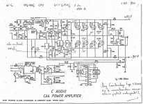
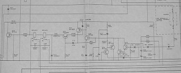
The schematic attached is from an old CA4 but it gives an idea of how the mosfets are wired. Note that the metal cases (sources) are the output. If you measure DC on these, the output protection will kick in. Also, the gates should have +/- 0.9V with respect to ground.
/Hugo
/Hugo
Attachments
Thanks for the schematic - that's helps a bit...
I've just realised that I've been a real dimwit ... Don't quite know what I was thinking, but somehow I've invented mosfets that have only a Gate and a Drain!!!
So I'd better test between Gate/Drain and the 'SOURCE'! Doh!
Given that I kinda missed the 'source' even though it's obvious, I reckon there's still a chance of a failed mosfet causing all my grief!
I'll check that, plus look for spurious DC and will report back!
Cheers
Jonathan
Hi Hugo,
It looks like I've got + and - 0.4vdc on the Gates, and no DC (>0.01v) on the sources.
I'm still puzzled by this.. I don't want to leave the amp on to long at any one time as the Soft-Start Resistor starts to get quite hot...
I'll keep working on this - I need to look at the diagram in more detail and test some more points.
Thanks
Jonathan
Hi Hugo,
It looks like I'm not going to get an easy fix for this :-(
The Power Amp section seems to be working just fine... I used a Burosch CD Test disc to put a 1kHz tone into the amp and hooked up my scope to the output stage (just before the relays). I get a perfect 1kHz on the scope, all be it with a large peak-peak voltage
As expected, a music CD also produced a very normal looking output.
So the Amp's going into protect mode, but there's no DC on the output and the main power stage appears to be fine. Regardless of what source I feed into the Amp, the VU meters remain permanently with two leds lit per channel.
None of the relays ever switch over - I can understand the output relays, but what about the Soft-Start resistor relay? Surely once the amp has come on, that should still switch over to bypass the resistor? (I presume that soft start doens't actually reduce the voltage sent to caps/mosfets, but simply provides a bit of 'ballast' to help avoid spikes on start up?)
Do you have some other ideas because I'm definitely getting out of my depth with this amp.
Many Thanks
Jonathan
Hi Dave,
Thanks for the input on this....
Interestingly enough I'm pretty certiain that the TO220 transistor (if it's Q45 in the following photo - http://dynamicdiscos.co.uk/AMP_Pics/Large/DSCF0203.JPG ) has already been worked on in the past as the soldering is clearly different.
(You can see flux left round the pins in this pic: http://dynamicdiscos.co.uk/AMP_Pics/Large/DSCF0184.JPG )
I did test it for shorts a while back and it seemed fine, I'll test it again though and I haven't checked the coils on the ouput relays yet...
Do you by any chance have a higher resolution picture of the circuit? The one you sent is useable enough, but none of the text is readable :-(
Do you have the entire schematic available for this Amp? It would be nice to get hold of it so I can perform future repairs on this amp, and perhaps help other people if they have the same series.
Many Thanks
Jonathan
- Status
- This old topic is closed. If you want to reopen this topic, contact a moderator using the "Report Post" button.
- Home
- Amplifiers
- Solid State
- C-Audio RA2000 Protection LED