Hello people,
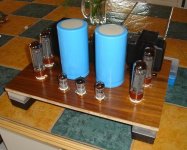
I plan to build a 4D32 single ended amplifier soon. I love the way 4D32 tubes look and I found a schematic that should provide a nice 20W output. The schematic is here :
http://members.at.infoseek.co.jp/lagarto/shishido/4d32.png
Could someone help me with the 2SC2335 setup? I understand that the 7 zeners are intended to produce a stabilized 336V to the screen, right? What about the 10Yd2.4 diodes? Are those zeners? Can't find this number anywhere... There a 3 units in parallel? They are used for emiter - base saturation?
Do you see another way to provide stable screen voltage?
Tell me if I'm right...
Looks like a standard basic vreg circuit.
I'd add the "reverse" protection diodes to that circuit, in case a tube decides to go south... you can find them in the app notes for basic three pin vregs.
Looks like the diodes "X3" are supposed to be three in series, probably to make sure the PIV is high enough.
You could use a resistor, since the purpose of the diode(s) or the resistor is to give the Zener string enough voltage & current to operate.
You can substitue any vreg circuit you like in place of the one they used.
One can make the case that a simple divider with or without a cap multiplier (the same circuit with a cap rather than a zener string), and/or a filter with a choke added is just as good sounding or maybe better sounding?
Another idea is to make a separate diode/filter arrangement off the primary with a choke input and see if that magically provides the necessary (lowered) voltage for the screens?
You might consider changing the drive circuit to be DC coupled, and or find another way to drive the tube in A2 rather than A1...
_-_-bear
I'm pretty sure that the diode shown on the collector of that transistor is just a current source. (current generator) Three of them in series are presumably to assure that the dissipation and voltage ratings of the devices is not exceeded.
I think the zener string is about 340V total. It is something of a brute force approach to supplying the screen. Below I am suggesting something even more brute force, but hopefully a lot more interesting..
You could probably replace that whole circuit with a couple (or 3) gas tube regulators.
0A2 - 150V
0B2 - 106 - 108V
0C2 - 68 - 83V
Strikes me that 3 0B2 in series would put you right in the ballpark. Total bias under quiescent (no signal) conditions should be near 30mA - the maximum rating of the 0B2, and must not fall below 5mA or the tubes will extinguish.
- Status
- This old topic is closed. If you want to reopen this topic, contact a moderator using the "Report Post" button.
- Home
- Amplifiers
- Tubes / Valves
- 4D32 SE amplifier... help!
