Ok so while I had no communications for a week I built the datasheet NIGC with an LM3875... testing on one speaker sounded okish but when I tested in on my main speakers it sounded reaply plastic to say the very least.
Weak bass, overemphasised top etc... Wanting to finish the amp now and get to the next stage I took the soldering iron to the stripboard and quickly wired up NUUK's IGC.
Now I'd be the first to admit Mauro's My_Rev puts the IGC to shame (appart from amount of bass), but the diffirence between the IGC and NIGC were even bigger.
I'm sure I read somewhere that inverted and non inverted topologies affects the bandwidth, could this be the reason?
I'm aware of the fact the gain in theory should be affected by a pot on the source, but thats exactly what I did, 10k Alps and --- no harm done - NUUK's IGC still makes the datasheet NIGC sound like a fart in the wind at both extremes of the pot (sorry neighbours).
I'm so put off non-inverted gainclones now its not funny.
Have any of you had good results with non-inverted setups?
What is your preferance?
I didn't touch the PSU or anything connected to the power pins during the swapover, only changed signal and feedback resistors and caps.
Hi,
I think the difference in input impedance may be a major reason for what you are hearing.
The non-inverting usually has a highish value of resistor from line to ground setting the input impedance//with stray capacitance//RF filter//input pin impedance. This resistor usually matches the upper leg NFB resistor.
The inverting input has an inline gain setting resistor that feeds into a virtual earth at the -ve pin of the amp. You cannot usually fit an RF filter here The other impedances in parallel are , I believe, smaller than on the non-inverting side, so they may have a bearing (but smaller) on the total effective impedance seen by the source.
However, the BIG difference is the usually small value of in line resistor. I think this will have a profound effect on how the source copes with the load.
the low input impedance of the IGC makes it imperative that you be careful with the wiring. i was playing around with one yesterday -- and it took up more time than I would devote to a small project -- I got the thing to oscillate at 1.2 MHz with only 10% THD ! OTOH, when you are careful with the wiring an IGC should have THD distortion ~ 0.006%

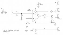
Just using datasheet schematic, or something you made yourself?
Just using a circuit I found somewhere.
")
Attachments
Nuuk said:
Just using a circuit I found somewhere.
What values for R 3, 4 and 6 are you using? Thanks!
Attachments
- Status
- This old topic is closed. If you want to reopen this topic, contact a moderator using the "Report Post" button.
- Home
- Amplifiers
- Chip Amps
- Inverted vs non inverted what is the whole story...?