Hi!
Is there anybody who knows or built the Nishiki amp??
The designer is Wim de Haan and the design was published in the September 2006 issue of AudioXpress.
More infos are in:
http://www.wdehaan.demon.nl/hybrid/nishiki/index.html
Greets:
Tyimo
Is there anybody who knows or built the Nishiki amp??
The designer is Wim de Haan and the design was published in the September 2006 issue of AudioXpress.
More infos are in:
http://www.wdehaan.demon.nl/hybrid/nishiki/index.html
Greets:
Tyimo
Hi Teodoro!
Not yet! Nobody knows this amp....
If I could get some positive info about the sound quality I would build it.
Greets:
Tyimo
Any news about it ?
Not yet! Nobody knows this amp....
If I could get some positive info about the sound quality I would build it.
Greets:
Tyimo
Tyimo said:
Is there anybody who knows or built the Nishiki amp??
The designer is Wim de Haan and the design was published in the September 2006 issue of AudioXpress.
More infos are in:
http://www.wdehaan.demon.nl/hybrid/nishiki/index.html
I am a subscriber to Elektor electronics magazine since 17 years.
And I have saved each issue. Have several 100 magazines full with electronics projects and schematics.
Some 10-15 years ago, was published such a HYBRID.
Tube voltage amp + Push-Pull Lateral MOSFET power buffer follower.
Push pull complementary MOSFET pair was working in Class AB.
No drivers, only the two mosfets!
And a usual VBE multiplier to set the idle currents in MOSFETS.
Like 100 mA, if I remember correctly.
VBE Multiplier and the GATES were fead by CCS, constant current sources.
---------------------
The coupling, from tube output to MOSFET Vbe-multiplier,
used two Film Caps.
One from tube to positive MOSFET, N-Channel Gate
and one from tube to negative MOSFET, P-Channel Gate.
---------------------
Supply was a bit lower voltage, than usual for tube. Like 100 volts maybe.
Think the tubes used were called PCC88 or PCC86 or something like that.
MOSFET supply was dual and so output could be adjusted for zero DC-offset.
---------------------
I could find that old Elektor article and take a close-up photo of the schematic.
If anybody is interested.
lineup
Hi Teodoro!
No, it is not problem! If you write to the designer Wim de Haan, he will send you the complet schematic.")
He is a very kind man.
Tyimo
It would be not so difficult to simulate it ... the problem is that the components values are hidden
No, it is not problem! If you write to the designer Wim de Haan, he will send you the complet schematic.
He is a very kind man.
Tyimo
teodorom said:Yes, please.
Thanks
Tyimo said:Hi Lineup!
Me too please!
Tyimo
Okay, I have a look into my many magazines
and try to find that very issue, may take some time
because 100 of magazines to search in.
But my guess hybrid article was around years of 1990-92.
The project was very complete.
With detailed supply circuits and even protection circuit.
And also every subcircuit had PCB layout and pictures of PCB, too.
I clicked your www homepage, teodorom.
You sure have a lot on the mathematics of Tubes.
I bet you have the most good SPICE simulations
anyone can do, when it comes to TUBES!
http://teodorom.atspace.com/
Think there are many tube lovers in Italy!
Think about Andrea Ciuffoli website!
Absolutely one of best TUBE SITES in THE WORLD:
http://www.audiodesignguide.com/
He has got some unique and good Solid State projects and schematics, too!
lineup
little audio amplifier website, under construction
http://lineup.awardspace.com/
Tube MOSFET Elektor Hybrid 1997
.
Okay,
it was 1997 this Tube MOSFET Elektor Hybrid was published.
What semiconductors are used?
-------------------------------------------
Tube:
PCC88
Voltage supply = 138 VDC
Heater: 7 Volt, or better one 300 mA constant current
---------------------
MOSFET, complementary output:
2SK176 + 2SJ56
at 100 mA idle current = Class AB
and 2 x 42 VDC supply
-------------------------------------------
Data:
65 Watt RMS into 4 Ohm
-1.7 dB at 100 kHz
___________________________
Comment from article:
Also 2SK175 + 2SJ55 can be used.
If lowering supply voltage ( 2 x 30 VDC )
it is said, that you can use IRF HEXFET:
IRF530 + IRF9530 or IRF540 + IRF9540
at about max 50 Watt output.
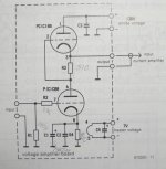
Attached is the very few parts Tube Circuit
The electrolytic capacitor C1 is 470 uF.
.
Okay,
it was 1997 this Tube MOSFET Elektor Hybrid was published.
What semiconductors are used?
-------------------------------------------
Tube:
PCC88
Voltage supply = 138 VDC
Heater: 7 Volt, or better one 300 mA constant current
---------------------
MOSFET, complementary output:
2SK176 + 2SJ56
at 100 mA idle current = Class AB
and 2 x 42 VDC supply
-------------------------------------------
Data:
65 Watt RMS into 4 Ohm
-1.7 dB at 100 kHz
___________________________
Comment from article:
Also 2SK175 + 2SJ55 can be used.
If lowering supply voltage ( 2 x 30 VDC )
it is said, that you can use IRF HEXFET:
IRF530 + IRF9530 or IRF540 + IRF9540
at about max 50 Watt output.
Attached is the very few parts Tube Circuit
The electrolytic capacitor C1 is 470 uF.
Attachments
Hello!
I'm also very interested in this thread because I would like to build a hybrid amplifier.
This schematic was published in a hungarian DIY book.
The tube stage stem from the famous Williamson amplifier with 2 6SN7 tube, and after the MOSFET part is very simple. The book's author wrote that he had built it and its sound was very good. I would like to use rather in A-class accordingly I have to decrease the supply voltage between +/- 12-15V.
I'm also very interested in this thread because I would like to build a hybrid amplifier.
This schematic was published in a hungarian DIY book.
An externally hosted image should be here but it was not working when we last tested it.
The tube stage stem from the famous Williamson amplifier with 2 6SN7 tube, and after the MOSFET part is very simple. The book's author wrote that he had built it and its sound was very good. I would like to use rather in A-class accordingly I have to decrease the supply voltage between +/- 12-15V.
nishiki hybrid amplifier
The intention of the so-called Nishiki hybrid amplifier is good sound and performance, this for a small budget.
I used Power MosFets like the BUZ900P and 2SK1058 family before in my hybrid designs, they are easy in use but also expensive. Though they have influence on the overall sound of the amp. An original high-performance power transistor like the 2SC5200 or 2SC3263 is only 3 euro or so, the used quasi-complementary output stage is very neutral in terms of sound and specs. Sound and specs depends on tube which is used, the circuitry and the coupling capacitors. I used several configurations with different tubes. The basic compound circuitry was build using the ECC82, ECC88 and 6N1P, all their own sound balance. All great, just different. I used a long-tail with a DC coupled cathode follower using the 6N3P, the ECC83 and 5965 (all this with a 6N1P as cathode follower), same story here. Balance and behaviour of the driver stage is very quick evaluated.
Lately I do use an ECL82 based driver based Nishiki concept and upto 100 watts distortion is as low as 0.15% (this with no overall feedback) and amp sounds like I know the ECL82; dynamic, no stress, open, great highs and lots of music.
I build several hybrid amplifiers using different driver tubes and different Power MosFets and I feel the Nishiki concept is the better choice. The overall cost will be lower and sound can be very entertaining.
Wim de Haan / NL
Looks like Wermona Regent 1000 with tubes and FETs instead of BJTs.
topicreader said:Hello!
I'm also very interested in this thread because I would like to build a hybrid amplifier.
This schematic was published in a hungarian DIY book.
An externally hosted image should be here but it was not working when we last tested it.
The tube stage stem from the famous Williamson amplifier with 2 6SN7 tube, and after the MOSFET part is very simple. The book's author wrote that he had built it and its sound was very good. I would like to use rather in A-class accordingly I have to decrease the supply voltage between +/- 12-15V.
Re: Elektor Hybrid
Was just waiting for somebody to ask.
Sometimes people ask about things
then forget about it all
and my help / service / reply
will be of no use
.... all I did
was waisting some of my precious lifetime
image shows your service man
in october 2006
lineup
lineup said:.
Okay,
it was 1997 this Tube MOSFET Elektor Hybrid was published.
What semiconductors are used?
-------------------------------------------
Tube:
PCC88
Voltage supply = 138 VDC
Heater: 7 Volt, or better one 300 mA constant current
---------------------
MOSFET, complementary output:
2SK176 + 2SJ56
at 100 mA idle current = Class AB
and 2 x 42 VDC supply
-------------------------------------------
Data:
65 Watt RMS into 4 Ohm
-1.7 dB at 100 kHz
___________________________
Comment from article:
Also 2SK175 + 2SJ55 can be used.
If lowering supply voltage ( 2 x 30 VDC )
it is said, that you can use IRF HEXFET:
IRF530 + IRF9530 or IRF540 + IRF9540
at about max 50 Watt output.
Attached is the very few parts Tube Circuit
The electrolytic capacitor C1 is 470 uF.
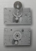
lineup said:.
Here is attached how the Tube PCB looks.
At a real photo!
See Circuit in previous post.
Tyimo said:Hi Lineup!
Would you post the output stage's circuit too???
Tyimo
Was just waiting for somebody to ask.
Sometimes people ask about things
then forget about it all
and my help / service / reply
will be of no use
.... all I did
was waisting some of my precious lifetime
image shows your service man
in october 2006
lineup
Attachments

- Home
- Amplifiers
- Solid State
- Nishiki hybrid amp