Anyone interested in buying my Aleph 5/30 Assembled Boards and Heatsinks?
Please make a sensible offer. Shipping is possible but I would need to find out the cost. I would prefer collection (from Leeds, UK).
DESCRIPTION:
Power Supply
Dual Mono power supply PCB with Hexfred rectifier bridge then 20KuF – 1.5mH – 30KuF filter per rail. Capacitors are 20 X 10uF 35V Panasonic TSU.
Measurements with 25-0-25VAC 300VA toroidal transformer (not included) at 242VAC mains and Aleph quiescent current of 2A:
700mV pk-pk of ripple (triangle wave) on the 20kuF capacitors and +/-33.8V RMS.
<30mV pk-pk of ripple (sine wave) on the 30kuF capacitors and +/-33.1V RMS.
DCR of inductor is approximately 0.4Ohms.
I would recommend a 22-0-22VAC 300VA transformer per channel to give approx 30V rails. This would reduce the heatsink temperature a bit as well as giving a better safety margin on the smoothing capacitors.
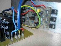
Amplifier Boards
Home designed PCBs with careful attention to grounding (separate power and signal grounds) and power supply layout. High current loops have minimal enclosed area and feedback traces carefully teed off (as per Doug Self’s recommendations). The circuit is the Aleph 5 with the Aleph 30 input configuration – this gives a higher input impedance that the Aleph 5. The Aleph 5 is thought by some (including NP himself) to be the best of the Aleph series combining the sweetness of the lower power models and some of the grunt of the larger ones.
3 IRFP244s each are used for the amplifier and current source, each set is matched for VGS within 20mV. The input IRF9610s are matched within 10mV for VGS.
The zener used in the current source for the differential pair has a 1uF decoupling capacitor added compared to the Alephs, NP now recommends this.
With supply rails of +/-33V and quiescent current of 2A per channel the power dissipation of 132W per channel is just about manageable with the heatsinks I used.
Input impedance is approx 40K Ohms (single ended). The PCB has the capability to accept the parts for a balanced input but they re not fitted.
Gain is approx X 12.5 (single ended) so a preamp with high gain is needed.
Power output is 60W according to the Aleph 5 service manual on 34V rails. The Aleph 30 claims 30W into 8R and 40W into 4R running on 25V rails, which seems more realistic.
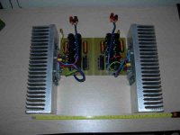
Heatsinks
300 X 100 X 65 (fin depth) pressed fin heatsinks should result in about 0.25degC/W is black anodised. This calculates out at a 33 degC rise for the 132W dissipation per channel. In practise the heatsinks, in silver, run at a guestimated 60 degC – i.e. just a bit too hot to keep your hand on. Adding a chassis and black finish would reduce this in a complete amplifier as would lower voltage transformers.
Parts Included
Input and output sockets.
Heatsinks with working boards X 2
Power supply board X1 (dual mono).
There is no chassis, transformers or mains parts.
Circuit diagram and layout foils.
Please make a sensible offer. Shipping is possible but I would need to find out the cost. I would prefer collection (from Leeds, UK).
DESCRIPTION:
Power Supply
Dual Mono power supply PCB with Hexfred rectifier bridge then 20KuF – 1.5mH – 30KuF filter per rail. Capacitors are 20 X 10uF 35V Panasonic TSU.
Measurements with 25-0-25VAC 300VA toroidal transformer (not included) at 242VAC mains and Aleph quiescent current of 2A:
700mV pk-pk of ripple (triangle wave) on the 20kuF capacitors and +/-33.8V RMS.
<30mV pk-pk of ripple (sine wave) on the 30kuF capacitors and +/-33.1V RMS.
DCR of inductor is approximately 0.4Ohms.
I would recommend a 22-0-22VAC 300VA transformer per channel to give approx 30V rails. This would reduce the heatsink temperature a bit as well as giving a better safety margin on the smoothing capacitors.
Amplifier Boards
Home designed PCBs with careful attention to grounding (separate power and signal grounds) and power supply layout. High current loops have minimal enclosed area and feedback traces carefully teed off (as per Doug Self’s recommendations). The circuit is the Aleph 5 with the Aleph 30 input configuration – this gives a higher input impedance that the Aleph 5. The Aleph 5 is thought by some (including NP himself) to be the best of the Aleph series combining the sweetness of the lower power models and some of the grunt of the larger ones.
3 IRFP244s each are used for the amplifier and current source, each set is matched for VGS within 20mV. The input IRF9610s are matched within 10mV for VGS.
The zener used in the current source for the differential pair has a 1uF decoupling capacitor added compared to the Alephs, NP now recommends this.
With supply rails of +/-33V and quiescent current of 2A per channel the power dissipation of 132W per channel is just about manageable with the heatsinks I used.
Input impedance is approx 40K Ohms (single ended). The PCB has the capability to accept the parts for a balanced input but they re not fitted.
Gain is approx X 12.5 (single ended) so a preamp with high gain is needed.
Power output is 60W according to the Aleph 5 service manual on 34V rails. The Aleph 30 claims 30W into 8R and 40W into 4R running on 25V rails, which seems more realistic.
Heatsinks
300 X 100 X 65 (fin depth) pressed fin heatsinks should result in about 0.25degC/W is black anodised. This calculates out at a 33 degC rise for the 132W dissipation per channel. In practise the heatsinks, in silver, run at a guestimated 60 degC – i.e. just a bit too hot to keep your hand on. Adding a chassis and black finish would reduce this in a complete amplifier as would lower voltage transformers.
Parts Included
Input and output sockets.
Heatsinks with working boards X 2
Power supply board X1 (dual mono).
There is no chassis, transformers or mains parts.
Circuit diagram and layout foils.
Attachments
- Status
- This old topic is closed. If you want to reopen this topic, contact a moderator using the "Report Post" button.