wellll.
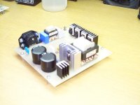
bridge rect from 115vac through cm filter. then a full bridge with mosfet into a large toriod with 16 t on pri and 4 t on sec to bridge ind/cap filter
the transistors are at home i guess i will have to get more info for the thread they are about 50 amp 600 volt.
jimbo
bridge rect from 115vac through cm filter. then a full bridge with mosfet into a large toriod with 16 t on pri and 4 t on sec to bridge ind/cap filter
the transistors are at home i guess i will have to get more info for the thread they are about 50 amp 600 volt.
jimbo
Topology
Hmmm,
Let's see. 20V @ 50A = 1kW. From 115VAC, we get ~162V. Assuming your design is good for low line of 90VAC (~127VDC), this is 7.85A. Through a full-bridge, the drain current is 1.56 I(max), or 12.25A. Giving a 20% margin, this is just under 15A.
Total conduction losses through the 4 MOSFETS will be I^2*R, or (15^2)A x say, 0.24W (Rds(on) for each MOSFET) gives 54W per MOSFET power losses, This doesn't take into account the switching losses, which will be a function of the MOSFETs' Rds(on) and the switching frequency. This is at the max of 50A.
At 25A, again at low line, this is (7.35^2)A x .24W = ~13W per MOSFET. Heatsinking will DEFINITELY be necessary.
Instead, I would do a conventional fullwave-doubler input off the AC mains, just like every AT & ATX PSU box does. Then, you will be dealing with ~320Vdc (~270VDC @ low line), and your (V^2)/R losses for each MOSFET (assuming you're using MOSFETs) is cut by three-quarters.
Then go on to either do a half-bridge, or full bridge. At 1000W, max, I would recommend the Full-bridge.
Or, if you really want to get wild, and further reduce your MOSFET drain currents, you could Active PFC the front-end, yielding a semi-regulated ~385V-400VDC. Your 600V units should handle 400V just fine. Then, with those decreased drain currents, you should be able to get your thermal problems under control.
At 1000W, I would strongly recommend PCF'ing to reduce the peak rectified currents that would result from the non-linear current waveforms that result from charging the input bulk capacitors at the peak of each haversine wavecrest. Also, PFC'ing instantly makes it compatible with all world voltages, without the need for a 115/230V switch.
Hope these little bits help you out.
Steve
yes of course , i should have thought of that.
i was looking at the L4981 or mc34262 for the PFC controller.
what are your thoughts on transformers? I am using a 2.4" toroid at 66khz, i belive that the primary is 16 turns made of 8x22ga. and the sec is 4 t of 36x22ga.
with the change in input voltage i will have to in creas the pri t to about 32ish.
i am using a 34025 for my switch controller with voltage control from a opto and current control through a current trans..
lets make a 5 kw for big stuff. \\
i am also working on a 12v to 115 invertor at 1.5 kw.........
thanks
jimbo
, i should have thought of that.i was looking at the L4981 or mc34262 for the PFC controller.
what are your thoughts on transformers? I am using a 2.4" toroid at 66khz, i belive that the primary is 16 turns made of 8x22ga. and the sec is 4 t of 36x22ga.
with the change in input voltage i will have to in creas the pri t to about 32ish.
i am using a 34025 for my switch controller with voltage control from a opto and current control through a current trans..
lets make a 5 kw for big stuff. \\
i am also working on a 12v to 115 invertor at 1.5 kw.........
thanks
jimbo
Wow, James. That's aggressive. (Not in this forum, though) 
I use the 33025 (Temp range of -40C to +105C) in current-mode control.
What is the material of the 2.400" toroid? For the #77 material (and this is getting old, as newer materials are supplanting it) at a frequency of 66kHz ( I will assume this is your switching frequency, and not the clock frequency, at 385-400V, by my calculations, your primary turns should be 40.38 (rounded to 40 Turns).
This equation comes from Chryssis' chapter on transformers:
N(pri) = (V(in) *e^8)/(k * f(sw) * B(max) * A(e), where:
N(pri) is the number of primary turns,
V(in) is the input voltage (Nearly constant for a PFC'ed front-end),
k is a constant (4.0 for sq waves, and 4.44 for sinewaves)
B(max) is the max flux density at the frequency
A(e) is the effective cross-sectional area of the core material.
From here, you can calculate the secondary turns.
For your PFC controller, the MC34262 is Critical-Conduction Mode (CrCM), which is good for power levels mainly below 200-300W. It is a variable-frequency control technique that is not best suited for power levels approaching 1kW.
I would look at the UC3854A Continuous Conduction Mode (CCM) PFC Controller. This constant-frequency PFC Chip is more suited to medium- and hi-power applications. Also, since both the PFC and the PWM chip are constant frequency, their oscillators can be synchronized to avoid producing beat-frequencies.
Consulting the Amidon Associates datasheets, for an FT-240-77 core, your max power throughput at 66kHz should be somewhere around 1200W. I don't have the portable sheets in front of me right now, and the main catalogue doesn't have this graph, but I think it is ~1200W. I will check when I get home.
So, for 66kHz, I would think your chosen core should be OK. .
As far as the Opto feedback, and current-transformer, those are both fine.
It sounds like you have already consulted several books on SMPS design. I smell Marty Brown's work here, maybe a little Abraham Pressman or the aforementioned Geo. Chryssis. These three books are my 'Holy Bible' in designing all of my SMPSs.
Methinks you are off to a goods start in the design process.
Steve
Wile E Diody
Intgreal Body diodes,
You can use some MUR880Es across each MOSFET, but I don't think it will be necessary, especially for constant-frequency current-mode PWM control.
Is 66kHz your switching or clock frequency?
Also, if you do consider PFC'ing the front-end, you will need to replace the normal standard-recovery rectifiers with ultra-fast rectifiers rated at at least 800V and 15A. The reason for this is now, there are high-frequency pulses being drawn from the AC line: XXkHz (whatever frequency the PFC is running at), modulated at the AC Line frequency of 60Hz.
I checked the Amidon Associates nomograph for the #77 ferrite toroids, and for the FT-240-77 (2.40" Ferrite Toroid, #77 material), at 66kHz, you have a theoretical ceiling of 1.5kW throughput. So, for 1kW, I think you have a satisfactory margin of safety. I would caution against letting the switching frequency get too high, as core losses will go up with higher frequencies. Another caution to take is when winding the primary and secondaries, you must provide for sufficient insulative layering between windings. I use teflon transformer tape, which works rather well. Actually, it's used for plumbing, but it works just as well for electrical applications, and I believe it also has a very high dielectric constant. Available at Homeless Depot or Lowe's.
As for "insanely hi power stuff", I guess right here. But please be aware, as you will be dealing with high AC & DC voltages (up to 400VDC and 240VAC) you MUST MUST MUST exercise EXTREME caution. I know you've probably already heard this, but it is necessary to repeat because of the danger involved.
This forum has strict rules about discussion of dangerous and potentially lethal topics (and reasonably so) . Discussion of this topic (Line-operated SMPSs) is, of course, permitted here, provided that proper cautions are mentioned, the proper precautions are taken, and that the poster(s) asking the questions demonstrate a reasonably good knowledge of what they're doing.
You will find that there are several SMPS gurus here in the forum (EVA, jackinnj, poobah, luks, chas1, just to name a few), and sooner or later they may chime in and give their thoughts. Lots of good advice here.
Steve
Re: Wile E Diody
That's not really required. The common practice is to add a small capacitor, say 100nF to 470nF depending on power level, across the + and - terminals of a standard diode bridge in order to prevent most of the HF current ripple from reaching the diodes. A considerably higher capacitance is obviously required at the AC side of the diode bridge in order to finish the filtering job.
Also, when multi-kilowatt outputs are required, sometimes it's easier to go modular and stack multiple smaller SMPS units with their outputs connected in series or parallel (depending on voltage requirements) and proper active current/voltage sharing.
N-Channel said:Intgreal Body diodes,
Also, if you do consider PFC'ing the front-end, you will need to replace the normal standard-recovery rectifiers with ultra-fast rectifiers rated at at least 800V and 15A. The reason for this is now, there are high-frequency pulses being drawn from the AC line: XXkHz (whatever frequency the PFC is running at), modulated at the AC Line frequency of 60Hz.
Steve
That's not really required. The common practice is to add a small capacitor, say 100nF to 470nF depending on power level, across the + and - terminals of a standard diode bridge in order to prevent most of the HF current ripple from reaching the diodes. A considerably higher capacitance is obviously required at the AC side of the diode bridge in order to finish the filtering job.
Also, when multi-kilowatt outputs are required, sometimes it's easier to go modular and stack multiple smaller SMPS units with their outputs connected in series or parallel (depending on voltage requirements) and proper active current/voltage sharing.
Steve and Eva,
I am thinking about the diode bridge and with standard or uf recovery diodes. I suppose the UF diodes would be good if I were depleting the capacity of the doubler but if i were not a small cap would work I will have to do some overhead experiments to see how those little electrons and coulombs are getting along..
I was refering to diodes in series with the mosfets (i was unclear)
in http://www.diyaudio.com/forums/showthread.php?s=&threadid=69111&perpage=10&pagenumber=29
posts 289 and 290....
i was thinking that the instonaneuos reverse currents might be reduced.......saving mosfets..
I totally agree with safety as the most important aspect, after all if you kill yourself you cant keep playing.
When I was wil the Voice of America (VOA), we had some people die due to their unattentiveness, after all a megawatt transmitter operating at 30kv and 50 amps is not a good thing to commune with.
thank you both...
jimbo
Jimbo:
Diodes in series with MOSFETs: I have heard of using Schottky rectifiers of sufficient Ampacity. Since it is in series with and not across the +HV line, there is no need to use 600V Ultrafasts. This would address the concerns Instantaneous reverse current.
Diodes in the Main Rectifier bridge: I seem to remember somewhere that the main rectifiers should now be fast-recovery or ultrafast-recovery, because of the high-frequency pulses modulated at 50Hz or 60Hz are being drawn through them. I think it was Brown's chapter on PFC, or maybe it was an old Motorola (ONSemi) Application Note. Something like "Now the bulk input cap is reduced to 1-2mF, and the high-ripple pulse DC is fed to the PFC Converter circuit. This 1-2mF cap removes the high-frequency component in the RF range, but that's all. The xxkHz PFC component is still present.
However, if EVA says it's ok, then I would accept that as Gospel, and go with a conventional bridge.
[EDIT]: After going back and re-reading the PFC Section, I realize that you could have either MURs OR the 1-2mF cap after the std-recoveries. Having both would be redundant. Doh!
Regarding her comments on the really high power stuff, I have to agree that modularizing it, and putting the secondaired in series is easier. I can't believe I forgot this. I recently tried to fix a neighbor's 2500W Inverter and saw that each section (2- 1250W sections in parallel) used four smaller transformers, with their 40V secondaries in series. This ensures proper current sharing, and parallelling the filtered/rectified high-voltage DCs together was fed to the DC-AC 60Hz Bridge Output section.
Although this is for DC-AC step-up, the same principle applies for an off-line SMPS of multi-kW capacity.
Those diodes bypassing the own MOSFET body diodes are only required in certain situations in which the body diodes would be subject to hard switching otherwise. That's the case for class D amplifiers, motor drivers, and those phase-shifted bridges required to operate at very light loads, but *not* for conventional half and full bridges driving a transformer.
Body diodes have been always a huge pitfall in MOSFET transistors. They suffer from strong charge storage phenomena resulting in a very long and "peaky" reverse recovery process. Furthermore, if a certain dIrec/dt slope is exceeded during reverse recovery or a certain dV/dt slope is exceeded when Vds rises just after recovery, the MOSFET will LATCH itself into an ON state (routinely resulting in the four devices of a full bridge exploding).
High voltage MOSFETs are particularly prone to that failure mode in circuits involving any body-diode switching. That's because the performance of their body diodes is particularly poor and their Rds-on is not low enough in order to shunt the diode most of the time in order to prevent charge storage as it happens in low-voltage MOSFETs. That's a good reason for using IGBTs instead in troublesome circuits, altough there are new generations of high voltage MOSFET transistors with improved body diodes at the expense of higher Rds-on and prices. Check "C3" and "CFD" series from Infineon for instance.
Note that using the own MOSFET to shunt the body diode after it has been conducting may also lead to failure modes as it happens in phase shifted bridges at light loads. That's because charge may remain stored in the diode, thus keeping the recovery process unfinished until an attempt is made to turn off the MOSFET (and if the other side turns on too quickly and tries to "push" the diode above its weak limits... BOOM!!).
You may find some interesting reports googling for "mosfet body diode failure modes"
It's quite disappointing to see MOSFET devices flattered everywhere while their failure modes and weaknesses are just ignored. Most people know that an IGBT can latch itself into an ON state, but nobody seems to know that MOSFETs suffer from similar pitfalls. Also, nobody seems to know that high voltage MOSFETs also suffer from small current tails, like SMPS IGBTs, due to internal gate spread resistance (not all MOS cells are turned off at the same time).
pfc
Ok,
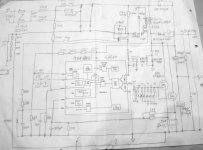
I believe that steve had posted a pfc jpg and i have searched for it with no luck.
i downloded i and looked over it and have a question....
there is a 1n5407 across the boost inductor. why? it seems as this would limit the lower voltage that the pfc could go to by creating a half wave rec bypassing the pfc.
i did not see that in the appnotes from ti or onsemi........
jimbo
Ok,
I believe that steve had posted a pfc jpg and i have searched for it with no luck.
i downloded i and looked over it and have a question....
there is a 1n5407 across the boost inductor. why? it seems as this would limit the lower voltage that the pfc could go to by creating a half wave rec bypassing the pfc.
i did not see that in the appnotes from ti or onsemi........
jimbo
Jimbo,
Here is that Active PFC. And here is the link to the original posting: http://www.diyaudio.com/forums/showthread.php?s=&threadid=52367
I started that thread, and it sparked alot of good exchanges and idea sharing. Look at post #14 & beyond............
Steve
Here is that Active PFC. And here is the link to the original posting: http://www.diyaudio.com/forums/showthread.php?s=&threadid=52367
I started that thread, and it sparked alot of good exchanges and idea sharing. Look at post #14 & beyond............
Steve
Attachments
What's the Frequency?
Jimbo,
Forgot to answer your other question: 83.3kHz (Osc) 41.6kHz for the transformer is OK, but you ar egood upto a couple of 100kHz before core losses become significant.
I finally dug up the equation for the frequerncy:
F(osc) = 1/[C(t) (0.7R(t) + 3R(d)], where R(d) is the deadtime resistor between pins 5&7. Mostly this is zero, but can also be 100 W/.
So say, for R(t)=2.21K, R(d)=0, and C(t)= 6800pF, your clock frequency will be:
F(osc) = 1/{0.01E-6 x [(0.7 x 2000) + (3 x 0)]}
= ~95kHz, or 47.5kHz on the transformer.

- Status
- This old topic is closed. If you want to reopen this topic, contact a moderator using the "Report Post" button.
- Home
- Amplifiers
- Power Supplies
- hi power smps