I need to build a regulated supply for 35v @ >5A and would like to use parts I already have.
I plan on using a LM317 with a pass transistor, but I only have NPN 3055's and not any PNP 2955's.
I have found this diagram of using a 3055 instead, but it looks a bit over simplified and I would like to know if it would even work or if theres anything else that needs to be taken into account.
Let me warn you I am about as novice as one can get.
http://www.diyaudio.com/forums/attachment.php?s=&postid=662888&stamp=1118719729

OK, I tested this with a 7912 and 3055; no other components, and it works great. The 7912 stays completely cold and the 3055 heats up as expected.
Is there any disadvantaged to doing it this way over the conventional method of using a 2955? This is so much more simple I can't see why you would want to use a 2955.
Also, if I wanted to parallel more 3055's do I need to put a current sharing resistor anywhere?
Thanks
Is there any disadvantaged to doing it this way over the conventional method of using a 2955? This is so much more simple I can't see why you would want to use a 2955.
Also, if I wanted to parallel more 3055's do I need to put a current sharing resistor anywhere?
Thanks
Ideally you'd want to put very low value resistors in series with the emitters of the transistors so they share the load current.
A neat trick would be to add those resistors in series with each emitter then connect the LM317s feedback resistor to that new output node.
That approach has some nice benefits.
A neat trick would be to add those resistors in series with each emitter then connect the LM317s feedback resistor to that new output node.
That approach has some nice benefits.
PNP's are used in low-drop out regulators, NPN's are used in standard regulators. In the low-dropout version you burn fewer watts -- but the output capacitor has to be selected more carefully.
Consider the LM317 as a "error amplifier with reference" -- this is what BWRX is suggesting in essence.
you can get away with an LM317LZ which is a 100 milliamp TO-92 if you use 2 of your pass devices in Darlington configuration --
Consider the LM317 as a "error amplifier with reference" -- this is what BWRX is suggesting in essence.
you can get away with an LM317LZ which is a 100 milliamp TO-92 if you use 2 of your pass devices in Darlington configuration --
Thanks for the help guys.
I have lots of LM317T and LM317LZ , but I think I'll stick with using LM317T to keep things simple... I need simple.
There are lots of examples of using a 2955 as a pass transistor for a LM317, but the only example of using a 3055 I can find is that simple diagram found on this forum.
I have lots of LM317T and LM317LZ , but I think I'll stick with using LM317T to keep things simple... I need simple.
There are lots of examples of using a 2955 as a pass transistor for a LM317, but the only example of using a 3055 I can find is that simple diagram found on this forum.
jackinnj said:Consider the LM317 as a "error amplifier with reference" -- this is what BWRX is suggesting in essence.
That's what I meant to suggest, but the way I described it in my last post will not work. I keep forgetting that these regulators mainting a constant voltage between the output and adj pins which causes a current to flow through the upper resistor and also the lower resistor which sets the reference voltage.
Attached is the basic version of what you want to construct, Mr. Anonymous1
The 100V was arbitrarily chosen. Obviously do not use an input voltage that high or parts will fry.
Attachments
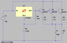

That resistor is just to get the desired 5A load at 35V. It's only for simulation purposes. It would need to have a rating of at least 175W if you were to actually test the regulator with it is as a load for an extended period of time.
Those 0.1ohm resistors will also dissipate right around 0.25W if the load does draw close to 5A. They should really be at least 0.5W. You could use lower values too.
To vary the output voltage you need to adjust R7. You can make R7 a little higher than what I have in the schematic (say 3k), put a larger value pot in parallel with it (about 100k for an R7 of 3k), and tweak the pot until you get the desired output voltage.
This scheme works because the 200 ohm resistor between the LT1084s output and adjust pin ensure that a constant current flows through the transitor and R7. That constant current sets a voltage across R7, which in turn sets the voltage between R8 and R9. That voltage causes a constant current to flow through R8 and thus R9 as well. That current sets the voltage across R8 and R9 which is the output voltage. The regulator is floating, in a sense, because the output voltage is set and Q4's collector soaks up the voltage variation from the varing current going through the bjt's and emitter resistors.
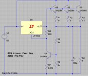
Now that I think about it, be carefult with the value I have the schematic because you're using an LM337 which has a different output-adjust pin voltage (the LT1084 has 1.25V). That will cause a different amount of current to flow which will change the output voltage. I think the LM337 has a 1.5V differential which means more current will flow and the output voltage will be higher, so you could use a higher value resistor between the output and adjust pins to lower that current back to around 6ma.
Those 0.1ohm resistors will also dissipate right around 0.25W if the load does draw close to 5A. They should really be at least 0.5W. You could use lower values too.
To vary the output voltage you need to adjust R7. You can make R7 a little higher than what I have in the schematic (say 3k), put a larger value pot in parallel with it (about 100k for an R7 of 3k), and tweak the pot until you get the desired output voltage.
This scheme works because the 200 ohm resistor between the LT1084s output and adjust pin ensure that a constant current flows through the transitor and R7. That constant current sets a voltage across R7, which in turn sets the voltage between R8 and R9. That voltage causes a constant current to flow through R8 and thus R9 as well. That current sets the voltage across R8 and R9 which is the output voltage. The regulator is floating, in a sense, because the output voltage is set and Q4's collector soaks up the voltage variation from the varing current going through the bjt's and emitter resistors.
Now that I think about it, be carefult with the value I have the schematic because you're using an LM337 which has a different output-adjust pin voltage (the LT1084 has 1.25V). That will cause a different amount of current to flow which will change the output voltage. I think the LM337 has a 1.5V differential which means more current will flow and the output voltage will be higher, so you could use a higher value resistor between the output and adjust pins to lower that current back to around 6ma.
theAnonymous1 said:Thanks for taking the time to help me out Brian.
No problem. Thanks for giving me something to think about while I was at work
Attached is the LT spice file if anyone is interesting in simulating. I like this circuit because it's not something I've seen before and it appears to work well (aka simulates well) and has high output current capability. I haven't done an FFT of the output voltage or tried to simulate a pulsed current load yet, but I'll have time tonight and tomorrow to check it out. Also the effect of input ripple.
I bet bypassing the adjust pin with a cap will improve noise a bit just like it does for a normal 3 pin regulator configuration.
Edit: Bypassing the adjust pin to ground does help the noise and squelches an oscillation that occured with lighter loads.
Attachments
That resistor is just to get the desired 5A load at 35V. It's only for simulation purposes. It would need to have a rating of at least 175W if you were to actually test the regulator with it is as a load for an extended period of time.
Told you I was a newb.
I kinda knew thats what it was for but had to ask just to be safe.
I just got a killer deal on 40 2N3055's ($18), so I can make all kinds of high current regulated supplies now.
theAnonymous1 said:Told you I was a newb.
I just got a killer deal on 40 2N3055's ($18), so I can make all kinds of high current regulated supplies now.
The real noobs are the ones that don't ask questions if they don't understand but want to.
That's a pretty good deal for those transistors. If you build the latest version I posted let me know how it works. I'd eventually like to use something like that to regulate the supply rails for a UcD180.
Hi,
the clever guys are the ones who recognise the gap in their knowldge and are not embarassed to ask and risk exposing their limits ( a common failing in the young and not so young).The real noobs are the ones that don't ask questions if they don't understand but want to
The circuit you posted "kinda" works - output voltage is regulator's output minus ~0.7V (Vbe), but that's not controlled by the regulator, so the quality is not too good.
Look at http://ourworld.compuserve.com/homepages/Bill_Bowden/page12.htm, "High Current Regulated Supply".
Look at http://ourworld.compuserve.com/homepages/Bill_Bowden/page12.htm, "High Current Regulated Supply".
AndrewT said:Hi Bwrx,
you have simulated using a very slow device.
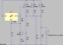
Do you have time to simulate using a power FET pass device?
I have lots of irf540.
LT spice has an IRF530, and it simulates quite nicely with those in place of the BJTs. The great thing about the latest circuit is that the voltage at the output of the 3 terminal regulator will adjust to whatever it needs to be so that the output voltage is what it is set to be.
With FETs you need to make sure you have a hih enough input voltage so the regulator has an adequate voltage to drive the gate of the FETs. Some power FETs require a Vgs up to 10V for them to fully be on. BJTs don't have such a requirement, they just need adequate base current drive.
For FETs it may be better to have a small resistor in series with each gate, and the source resistors may not be necessary. I just simply swapped FETs for BJTs from the previous circuit.
Attachments
- Status
- This old topic is closed. If you want to reopen this topic, contact a moderator using the "Report Post" button.
- Home
- Amplifiers
- Power Supplies
- pass transistor in regulated supply?