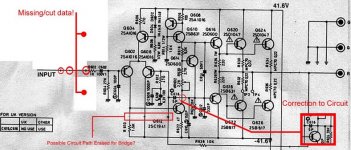
Rotel RB850 Schematic Errors
I have been researching the Rotel RB850 amplifier for several years.
I have compared it to the schematics of similar Rotel amplifiers.
I saw a schematic on this forum that seems to have at least one error.
It looked like a scan of a photocopy that had things erased.
I have redrawn the schematic based on the one on this forum,
similar ones found elsewhere, and my RB850.
I will answer any questions you may have (as far as I know).
There is a thread with this similar question on this forum
Sincerely,
Chris Browne
Ground Noise Industries
What are the mods you did on this amp?
Hi Gni,
What are the mods you did on this amp? I have a vector research integrated amplifier VA-100 with exactly the same power amplifier stage, and would like to tweak that amp. How does this amp sounds? and the tweaks improved the sound?
Thanks,
routhun
Hi Gni,
What are the mods you did on this amp? I have a vector research integrated amplifier VA-100 with exactly the same power amplifier stage, and would like to tweak that amp. How does this amp sounds? and the tweaks improved the sound?
Thanks,
routhun
Hi Chris,
You should install a new 270° unit at the very least, or put the old one back in after cleaning the slip ring and wiper.
What you people fail to realize is that the multiturn types generally have a much smaller contact area and are not intended to pass DC current.
I'm actually getting tired of hearing about this ill informed "upgrade".
-Chris
I am doing my best to figure out why you would do that.I replaced the single turn bias adjust pot with a 15 turn unit. . .
You should install a new 270° unit at the very least, or put the old one back in after cleaning the slip ring and wiper.
What you people fail to realize is that the multiturn types generally have a much smaller contact area and are not intended to pass DC current.
I'm actually getting tired of hearing about this ill informed "upgrade".
-Chris
Anatech??, a multiturn trimpot is nothing but a single turn with a screw and a cog to allow easier adjustment than a very cheap open frame single turn trimpot. Its the same thing, just imagine a single turn, sideways and enclosed in a pretty sealed case thats helps protect from dust and dirt buildup.
Colin
Colin
Colin,
I think most of 'em are rated only to 50mW, which means you can put about five volts max across them at 10mA.
And I suspect that with the fine contact area, this point is the thermal weak link and eventually, even at 50mW, you get a few failures after a number of years.
The fine contact area is necessary because of the high sensitivity.
Like everything, more of this, less of that.....
Hugh
The original single turn was a 2.2K - I would eventually like to put
a smaller value unit - 500 ohm. It takes less than two turns of the
multi-turn for the bias go from zero to way too high (30mV).
All this is leading up to:
Front mounted millivolt meters and front mounted bias adjustments.
The problem I found with the single turn was that it would jump
from 6 mV to 9mV in the main area of adjustment. . . Once I narrow
down the smaller value pot. . .sure I can return to single turn. . . I
would want to create some sort of 'enclosure' to protect it.
One advantage of the multiturn is it sits above the main circuit
board so it is easier to get to when adjusting.
Again. I can send the schematic to anyone who needs it. . .or as
Rotel. . .
Just did some critical tests on the amplifier:
Resistor R619/620 and VR601/602 Bias Adjustment.
The R619/620 is a 2.7Kohm and VR601/602 is a 2.2Kohm
single turn trim pot(currently testing with a 2.5kohm multiturn.
Therefore a max R of 4.9kohms. . .
I am going to replace the 2.7Kohm with a 3.6kohm resistor; and
replace the 2.2kohm pot with a 500kohm pot. Therefore a new
max R of 4.1kohms. . . .more than enough to kill all bias.
Spec for bias is 4mV across the 0.22ohm output resistor. . .at that
rate the R619/620 and VR601/602 average 3920 ohms. . . a 3.6k
ohm with a 500ohm trimmer will put the trimmer
at 320 ohms--or about 60% of the turn--for spec bias.
When setting the bias up to 14mV, the R619/620 and VR601/602
average was 3660 ohms. . . the trimmer would only supply about
60 ohms to the total. . . the bias current would be about 64mA. . .
and couldn't go any higher--safer in the long run.
The left and right channel had a difference of about 100 ohms
when comparing the R619/620 and VR601/602 sum. . . the
left channel always required about 100 ohms more on the trimmer
to get the same bias current as the right channel. . . that is just
under 3% more resistance. . .less than 1/3dB for resistance. . .
There is about 600mV across the pair in operation; that is in the
<200 microamp range. . .very low current. . .never should be a
problem with a 20 turn trimmer, the current is just too darn low.
Will try to complete the exchange of parts Saturday. . . we have
a great electronics supply house just 12 miles down the road. . .
walls of 1/4W, 1/2W, 1W metal films in just about every value. . .
great trimmer selection also. . .
I will return to the single turn trim pot as anatech has suggested. . .
but in this current range. . .I don't think it would make a difference.
But I acknowledge anatech. . . his advice has proven good time
and time again. . .
See you all tomorrow.
Hi Chris,
 Any guesses why?
Anyway, I've done what you are suggesting a few times when the design team allowed too much range in the adjustment. Not everyone was so sloppy. They do not need protecting either. The problem is the buildup of oxides. This is easily prevented with some contact cleaner. The area of trouble is in the metallic contacts.
So, install good 270° controls and be happy. You may need to clean them in 20 years I guess.
Hi Colin,
Please think about what people say when they make a comment that seems to center around price and questionable benefits of a component. If you use some common sense when you are thinking, you may get to the truth of the matter. Dust is normally not an issue. If it is, then there are other problems on the circuit board that overshadow the alleged dusty control. This is a non-issue.
Hi Ashok,
Yes, nailed the problem. That and contact pressure and the very small contact area coupled with a slow moving contact. No chance to break the oxide layer that will form at some point.
-Chris
We used to call that "Yamaha syndrome".The problem I found with the single turn was that it would jump from 6 mV to 9mV in the main area of adjustment. . . Once I narrow down the smaller value pot. . .sure I can return to single turn. . . I would want to create some sort of 'enclosure' to protect it.
Any guesses why?Anyway, I've done what you are suggesting a few times when the design team allowed too much range in the adjustment. Not everyone was so sloppy. They do not need protecting either. The problem is the buildup of oxides. This is easily prevented with some contact cleaner. The area of trouble is in the metallic contacts.
So, install good 270° controls and be happy. You may need to clean them in 20 years I guess.
Hi Colin,
I'm sorry to disagree with you. There has been much talk about "cheap" single turn controls. Some may be cheap, but there are many good ones out there. News flash. There are cheap multi turn controls also. Oxidation is your problem here mostly, and wiper contact tension. You would need a hermetic, gas filled control to avoid the oxide issue. Good tension requires a robust assembly in a tiny package. Hmmmm. They are not designed to pass current, the contact area is simply too small.a multiturn trimpot is nothing but a single turn with a screw and a cog to allow easier adjustment than a very cheap open frame single turn trimpot. Its the same thing, just imagine a single turn, sideways and enclosed in a pretty sealed case thats helps protect from dust and dirt buildup.
Please think about what people say when they make a comment that seems to center around price and questionable benefits of a component. If you use some common sense when you are thinking, you may get to the truth of the matter. Dust is normally not an issue. If it is, then there are other problems on the circuit board that overshadow the alleged dusty control. This is a non-issue.
Hi Ashok,
Yes, nailed the problem. That and contact pressure and the very small contact area coupled with a slow moving contact. No chance to break the oxide layer that will form at some point.
-Chris
Hi Anatech,
For myself the price was never the attractive part, considering the multiturn pots are atleast 10X the price. The biggest advantage of course is the fine adjustment, sneeze with a 1-2k single turn and you end up quite out of whack on your settings, critical when trying to set bias, or offset, For VBE, in this case it neither sees much current nor voltage. But you are right in a large sense, practically every upgrade out there recommends replacing all trimpots with multiturn pots and to be honest I never had thought too much about the issues you bring up which did find myself checking out the datasheets for the 3296,3266 series again.
For myself the price was never the attractive part, considering the multiturn pots are atleast 10X the price. The biggest advantage of course is the fine adjustment, sneeze with a 1-2k single turn and you end up quite out of whack on your settings, critical when trying to set bias, or offset, For VBE, in this case it neither sees much current nor voltage. But you are right in a large sense, practically every upgrade out there recommends replacing all trimpots with multiturn pots and to be honest I never had thought too much about the issues you bring up which did find myself checking out the datasheets for the 3296,3266 series again.
Hi Colin,
Well, often the thing that makes the most difference to people is that the recommended part is different in some way.
Mind you, it's cheaper and easier to go large with the range of adjustment and let the technicians worry about it. That still does not make the 270° control bad. It's more a statement on the design.
Also, consider that some multi-turn controls have play in the worm assembly. So do some 270° types, but at least you can see what's happening.
Ever try to optimize a piece of test gear with dirty 10 or 20 turn controls? It isn't fun and replacement is required. Often this occurs before the 270° types. Not a ringing endorsement for their use (multi-turn types).
-Chris
Well, often the thing that makes the most difference to people is that the recommended part is different in some way.
Well, now you are talking adjustment range. When I design something that needs adjustment, I figure in where I will be at the limits and add a little room for my adjustment. Then I built it and confirm I got it right. In a properly designed circuit, the trimmer will not act as you describe.The biggest advantage of course is the fine adjustment, sneeze with a 1-2k single turn and you end up quite out of whack on your settings, critical when trying to set bias, or offset
Mind you, it's cheaper and easier to go large with the range of adjustment and let the technicians worry about it. That still does not make the 270° control bad. It's more a statement on the design.
Also, consider that some multi-turn controls have play in the worm assembly. So do some 270° types, but at least you can see what's happening.
Ever try to optimize a piece of test gear with dirty 10 or 20 turn controls? It isn't fun and replacement is required. Often this occurs before the 270° types. Not a ringing endorsement for their use (multi-turn types).
-Chris
Hi,
As well known, VBE multipliers over compensates so they are something in between constant current and temperature regulators, hopefully more of the first.
Now, if one set bias very exactly with a multiturn pot, readjust several times as temperature rise until all is stable. Then put the lid on the amp and temperature rise further, bias will then have a new value, there goes that precision the multiturn "provided".
I for one appreciate the great “feel” that a good single turn provides.
And yes, when all bias comes within a few degrees of viper turn is very familar. Makes your work "more exiting"
I have two Yamaha M-45s with the "Yamaha syndrome!"
Drives me crazy setting the bias. . .it just seems to drift with the
wind. . . any air exchange in the amp case and the bias drifts again.
My M-45s don't like metal adjustors. . .just getting one close to the
trimmer and the bias changes. . . .
Just blew out the right channel in one of my M-45s. . . need to add
test points. . .dropped alligator clip on exposed jumpers. . .pop. . .
that was it. . . need to add protection to jumpers. . . another thread.
Might just put a fixed resistor in place of the trimmer and let the
bias drift a little. The resistor is 2.7kohms with a 2.2k trimmer.
4mV is spec for the rotel RB850
Right Channel (total Bias Resistance = R620+VR602)
3870 ohms produced bias of 4.1mV (18mA)
3608 ohms produced bias of 14.2mV (64.5mA)
3476 ohms produced bias of 22.4mV (100mA)
394 ohm difference from high to low
Left Channel (total Bias Resistance = R619+VR601)
3970 ohms produced bias of 4.3mV (19mA)
3709 ohms produced bias of 14.0mV (63.4mA)
3578 ohms produced bias of 21.9mV (995mA)
392 ohm difference from high to low
- Status
- This old topic is closed. If you want to reopen this topic, contact a moderator using the "Report Post" button.
- Home
- Amplifiers
- Solid State
- Rotel rb850