Hi all,
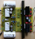
I'm finishing the construction of the mini-Zen headphone amplifier proposed by Tortello (diyaudio link, headwize link). Actually I followed a modified part list found on PT sound lab with Digi01's board in mind. Thanks a lot to them
The amplifier will feed a Sennheiser HD600.
I'm now trying to set the bias current. According to Tortello's original description the bias current could be a bit lighter then 210mA for higher impedance headphones. I set it to 180mA.
Now I have some questions...
- Is 180mA a good bias current to feed the HD600 or is it possible to go even more down (the limit is 100mA)?
- I let the amplifier for about 30min without any input signal and without any charge connected to the output. The heatsink became quite hot while I expected it to be only warm if one consider that in other versions of this amplifier the transistors can be just attached to the box without any special heatsink. Are the transistors supposed to become really hot?
Thanks in advance for your advices
r_jik45
I'm finishing the construction of the mini-Zen headphone amplifier proposed by Tortello (diyaudio link, headwize link). Actually I followed a modified part list found on PT sound lab with Digi01's board in mind. Thanks a lot to them
The amplifier will feed a Sennheiser HD600.
I'm now trying to set the bias current. According to Tortello's original description the bias current could be a bit lighter then 210mA for higher impedance headphones. I set it to 180mA.
Now I have some questions...
- Is 180mA a good bias current to feed the HD600 or is it possible to go even more down (the limit is 100mA)?
- I let the amplifier for about 30min without any input signal and without any charge connected to the output. The heatsink became quite hot
while I expected it to be only warm if one consider that in other versions of this amplifier the transistors can be just attached to the box without any special heatsink. Are the transistors supposed to become really hot?Thanks in advance for your advices
r_jik45
Attachments
r_jik45 said:- Is 180mA a good bias current to feed the HD600 or is it possible to go even more down (the limit is 100mA)?
Norminal impedance of HD600 is 300 ohms.
So, I drive HD600 with rather high voltages (P = V^2/(2R)).
I do not need high current (P = I^2*R/2).
And... maybe better to ask now:
I'm not in the electronic field (but DIY is fine).
Could somebody give me a simple explanation regarding what is this bias current and the good/bad points setting it high or low?
(what I found is too much electronic specialist oriented so I did not really understand )
)
Thanks in advance for that!!!
I'm not in the electronic field (but DIY is fine
).Could somebody give me a simple explanation regarding what is this bias current and the good/bad points setting it high or low?
(what I found is too much electronic specialist oriented so I did not really understand
)Thanks in advance for that!!!
I understand that the bias refers to a fixed dc voltage or a constant current source that sets the operating conditions for semiconductor devices. And, the bias refers not only to its amount, but also its direction--i.e. forward bias or reverse bias.
As you know, your amp gets life of Class-A by a Papa's special current source bias of Class-A that works as a constant current source on idling condition, but . . . wow! . . . automatically coverts into an active current source whenever it sees any ac signal. No more ac signal? Then, it comes back to the constant current source bias. It is an efficient way of biasing, which is efficiently boosting ac signal current into the output loads (speakers or headphones).
Many diyers claim that more indling current improves the sonic quality of amps. Meanwhile, I would like to say that the size of Vds is also affects the sonic quality of them. Therefore, I believe that the desirable sonic quality could be got by a reasonable compromise between the size of Vds and idling current.
Hi all,
Seems I need your help again...
I've lowered the bias current to 150mA.
I connected the potentiometer the wrong way; the volume decreases instead of decreasing when I turn the potentiometer from left to right. Well it's a minor problem for now.
I tried the amplifier with an headphone (balance not adjusted yet)... and realized that there is a big 'noise/hum'.
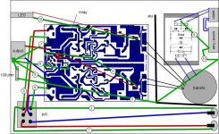
I made a scheme of the ground connections in order to see if there could be a problem there. The numbers refer to:
1. Ground right input (connector to pot.)
2. Ground left input (connector to pot.)
3. Ground right input (pot. to pcb)
4. Ground left input (pot. to pcb)
5. Ground resistance to case
6. Ground to mute outputs (relay)
7. Ground right output
8. Ground left output
9. Ground socket to filter
10. Ground socket to case
11. Ground (12V supply for relay)
12. Ground (12V supply for LED)
There is an aluminium sheet between the transformer/filter and the main pcb. It's connected to the case.
I cut the connection '4' between the potentiometer and the right input (pcb) but the hum is still there. Is it ok to keep the ground between the input connectors to the potentiometer or should I wire it directly to the ground-inputs on the pcb?
Another point is that the heatsink (where the transistors are connected to) is not connected to the ground. Should I connect it?
These are the things I'm thinking of...
What is your opinion regarding this wiring? Or what do you think I should do to stop this hum?
In case, the amplifier can be seen HERE .
Thanks in advance for your help... and have a nice end of weekend,
Seems I need your help again...
I've lowered the bias current to 150mA.
I connected the potentiometer the wrong way; the volume decreases instead of decreasing when I turn the potentiometer from left to right. Well it's a minor problem for now.
I tried the amplifier with an headphone (balance not adjusted yet)... and realized that there is a big 'noise/hum'.
I made a scheme of the ground connections in order to see if there could be a problem there. The numbers refer to:
1. Ground right input (connector to pot.)
2. Ground left input (connector to pot.)
3. Ground right input (pot. to pcb)
4. Ground left input (pot. to pcb)
5. Ground resistance to case
6. Ground to mute outputs (relay)
7. Ground right output
8. Ground left output
9. Ground socket to filter
10. Ground socket to case
11. Ground (12V supply for relay)
12. Ground (12V supply for LED)
There is an aluminium sheet between the transformer/filter and the main pcb. It's connected to the case.
I cut the connection '4' between the potentiometer and the right input (pcb) but the hum is still there. Is it ok to keep the ground between the input connectors to the potentiometer or should I wire it directly to the ground-inputs on the pcb?
Another point is that the heatsink (where the transistors are connected to) is not connected to the ground. Should I connect it?
These are the things I'm thinking of...
What is your opinion regarding this wiring? Or what do you think I should do to stop this hum?
In case, the amplifier can be seen HERE .
Thanks in advance for your help... and have a nice end of weekend,
Attachments
r_jik45 said:But I thought that maybe an obvious mistake could be seen . . .
Understood . . .
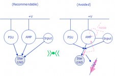
From the picture showing your PCB board, I assume that PSU and AMP are there all together in one board. It means that AMP's grounding path might be mixed up with PSU's grounding path carrying all dirty electrons before cleaned up. By using a small knife or a sharp tool . . . I would cut off all PSU grounding path and separate it from the AMP's grounding path, and send the separated grounding wire of PSU directly to the star ground.
I hope this will help.
hi
I agree with Babowana.
Hum is the sound of remains of 50Hz ( 60Hz ) from MAINS AC.
Sometimes, Often! ... this is doubled to 100Hz ( 120 Hz ) after rectification and power supply filter.
Amplifier amplify.
So even quite low levels of this 100 Hertz
reaching input
will be possible to listen to, hear, in speakers.
When is a hum
we will try to see: in what improper way is Sound of TRAFO
getting into contact with INPUT transistor.
Sometimes, in small boxes,
and especially when you use NOT toroid trafos
it can simpy be Trafo being too close to amplifier board.
Or too close to some wire, that is connected to input.
Babowana is having a fair idea of the cause.
Based on what we can read in this forum,
9 times out of 10
-- this hum is is transported
via GROUND ( 0 volt ) wires or PCB tracks or Metalbox, amplifier case
from TRANSFORMER ....... to INPUT of amplifier.
Cutting and re-arranging 0 Volt / Ground wires
will fix these issue quickly in those 9 cases.
Case number 10 out of 10 is the more mysterious one.
But also this will be solved, if not by brain and experienced helpers,
so by trial-and-error method for fixing.
lineup - haikku haikku
Thanks to both of you for your suggestions/comments.
For the 0V - signal ground connection, it seems that they are also connected on the original board proposed by Tortello. I will try to see if I can 'cut' it somewhere... even if I do not really know how to make the difference between them
Regarding the position and possible interaction/interference between the 50Hz source and the inputs: I will try to isolate them better. The transfo is indeed close to the inputs... but there is not much space to do organize the parts another way.
And what about the fact that the input-ground is connected directly to the potentiometer? Is it normal that way?
Anyway thanks again
r_jik45 said:... even if I do not really know how to make the difference between them
The attached sketch might help . . .
Whatever their sizes are, R is R and I is I . . .
And, AMP's role is amplfying the samll v=ir into bigger . . .
Attachments

- Status
- This old topic is closed. If you want to reopen this topic, contact a moderator using the "Report Post" button.
- Home
- Amplifiers
- Pass Labs
- One more mini Zen... almost!