I'm about to build an ECC81/12AT7 differential phase-splitter and I am looking for a simple and cheap (and european aviable) CCS like the LM317, but in the range of a few mA.
Any ideas ?
(This with or without a negative supply, better, reuse the planned DC filament supply 6.3 or 12.6v)
Any ideas ?
(This with or without a negative supply, better, reuse the planned DC filament supply 6.3 or 12.6v)
Here it is:
http://www.giaime.altervista.org/CCS.gif
feel free to use mostly any transistor you have at hand (that will survive the voltage and current needed, of course).
-16V can be obtained from 6.3VAC filaments with a voltage doubler.
http://www.giaime.altervista.org/CCS.gif
feel free to use mostly any transistor you have at hand (that will survive the voltage and current needed, of course).
-16V can be obtained from 6.3VAC filaments with a voltage doubler.
http://www.ixys.com/pdhvcr01.html
See Pete Millet's site for perfomance numbers. Easily available mail order.
See Pete Millet's site for perfomance numbers. Easily available mail order.
Thank you very much, it seems to answer so quicky to what I was lookink for (I'm a few hours' fresh member of the forum).
But Giaime, it's too bad that your link is not working at now, (either the one to RDH4).I got a big bag of BC337 will it fit to that circuit ? (that I haven't seen)
I saw also some data about tl431 (I got some of them) but I don't know if it realy needs a transistor (as said in the datasheet) or if it can be directly used like the lm317 for current up to 4mA? (3.52mA where simulated with ECC81(differential common cathode B+=292 Ra=82k Ua=175V), any thoughts ?
thx again
bembel said:I'm about to build an ECC81/12AT7 differential phase-splitter and I am looking for a simple and cheap (and european aviable) CCS like the LM317, but in the range of a few mA.
Any ideas ?
(This with or without a negative supply, better, reuse the planned DC filament supply 6.3 or 12.6v)
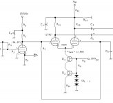
For something like this, just cascode a couple of BJTs. That's what I did (shown here). The two BJTs are MPSA42 high voltage, video amp, types to avoid possible poofage by overvolting. This works with two sections of a 6SL7 to form a differential phase splitter. Simple, and it works just great in maintaining both amplitude and harmonic balanve between sections. A 12AT7 will require a bit more current than a 6SL7, but still under 10mA. Keep the grids near ground, and add a negative rail voltage of about 20Vdc, and just about any small signal NPNs will get the job done.
Attachments
I got a big bunch of BC337, otherwise, I was wondering what was the difference between: bipolar , FETs , & ICs
I mean, how does the impedance of the CCS affects the circuit ? and then, which technology of component offert the best ratio
simplicity(laziness)/impedance,PSRR(good sound) ?
RDF suggestion about IXYS IC is a very pleasing idea too, but I was initialy thinking of a CCSink (in the cathode circuit). but it seems that this kind of component can work with low voltages too, any experiences about ?
Also it would be a nice thing from the CCS to be satisfied whit a negative rail of (-6.3 or -12.6V as I planned a DC filament supply for this phase-splitter stage)
Consider the LM334Z. I think that it does 10 mA max, but works very well with low voltage. Negative voltage is not always required. I tried it with a 12AT7 in LTP. I think that it sounded better tied to -5volts instead of ground. I get -5volts by rectifying the filament voltage and using a negative regulator.
Morgan Jones uses this chip in some of his designs. If you have the third edition look on pages 476, 477, 478, and 484.
The IXYS chip needs a little more voltage to work well, something like -12 volts.
Morgan Jones uses this chip in some of his designs. If you have the third edition look on pages 476, 477, 478, and 484.
The IXYS chip needs a little more voltage to work well, something like -12 volts.

bembel said:I got a big bunch of BC337, otherwise, I was wondering what was the difference between: bipolar , FETs , & ICs
BJTs work better as a constant current source than do most FETs. The current stays more constant with voltage variations. Also, since the BJT is a much higher gain device, the impedance of the BJT CCS is also higher. An IC would have even higher gain, since it's usually composed of several BJT gain stages. Cascoding the BJTs is helpful in getting the impedance up, and helps to avoid high frequency AC from flowing around the CCS. An IC is a good way to go, but I didn't have one, and did have the necessary transistors, so that's what I did.
I mean, how does the impedance of the CCS affects the circuit ?
The higher the impedance, the better the balance, both AC as well as harmonic distortion, and the higher the CMRR, which is important for rejecting whatever noise may be coming from the CCS in the tail.
and then, which technology of component offert the best ratio
simplicity(laziness)/impedance,PSRR(good sound) ?
RDF suggestion about IXYS IC is a very pleasing idea too, but I was initialy thinking of a CCSink (in the cathode circuit). but it seems that this kind of component can work with low voltages too, any experiences about ?
Also it would be a nice thing from the CCS to be satisfied whit a negative rail of (-6.3 or -12.6V as I planned a DC filament supply for this phase-splitter stage)
No easy answers there. If you need something with a low drop out voltage, then some of the aforementioned ICs would probably be the best way to go.
bembel,
I take it that your LTP splitter is not directly coupled to a previous stage, as in Miles's circuit? If it is, then you clearly don't need a negative supply.
What you could do, to avoid having a negative supply and also to give yourself a wide choice of CCS types, is to raise the grids (and coupled cathodes) above ground potential.
You can do this by arranging a potential divider from B+ to ground, using high value resistors of several hundred kilohms. Connect the "grounded grid" of the long tail pair (LTP) to the tap on the potential divider and also a capacitor (say 0.33uF) from that grid to ground (so that it is still grounded as far as the signal is concerned).
Then you need to have a 1Meg resistor between the two grids of the LTP, so they are at the same potential. The existing resistor betweeen the input grid of the LTP and ground must be removed. You will also need to use a coupling capacitor (say 0.047uF) as input to the LTP, since its grids are now elevated above ground potential.
Choose the resistors in the potential divider to give enough voltage at the grids and cathodes for your choice of CCS. You could even use a pentode CCS if you wanted to.
thank you all, for those helpfull answers!
maybe i can give you some more details about my planned amp:
---> input (with a switchable input cap only used for olds CDplayers with an offset)
---> differential ECC81/12AT7 (B+ 292V Ua=2*146V Ra=2*82k Uk<2V DC-heated)
---> coupling cap
---> EL84/6BQ5 PP (AC-heated ultra linear Z=8k CCS on common cathodes with balance pot (LM317 to ground))
---> finaly a switchable NFB to the grounded grid off the diff input stage (throught a 1k/10k divider and a 1nF bypass)
...So Ray's idea of direct coupling (raising Ug with a divider) is very nice, but what about the NFB then ? it finaly add two caps at input instead of the two coupling caps. Also I use an 230/240V isolation transformer and my B+ is limited so I can not raise the voltage so much anymore.
The voltage on the diff stage cathode is <2V for Ik=3.5mA (both halves), so too short for an IC to ground I think.
But I planned to feed the diff stage with DC-filament supply (I don't know yet if it will be 6.3V or 12.6V, but 6.3V will be easier anyway(than adding a separate transformer))
with the positive filament side tied to ground, thus connecting the CCS output to the -6.3V DC filament supply.
Any comments ? do you think this idea of filaments connection suits my needs, is -6.3v enought for IC chips (ixys or LM334Z), and also how big the -6.3V decoupling caps needs to be for two ECC81/12AT7 (stereo so 4*150mA@-6.3V + 2*3.5mA from CCSs)
Thx again, especially to Miles detailled explication too, I hope my english is not too hard to decode for you.
maybe i can give you some more details about my planned amp:
---> input (with a switchable input cap only used for olds CDplayers with an offset)
---> differential ECC81/12AT7 (B+ 292V Ua=2*146V Ra=2*82k Uk<2V DC-heated)
---> coupling cap
---> EL84/6BQ5 PP (AC-heated ultra linear Z=8k CCS on common cathodes with balance pot (LM317 to ground))
---> finaly a switchable NFB to the grounded grid off the diff input stage (throught a 1k/10k divider and a 1nF bypass)
What you could do, to avoid having a negative supply and also to give yourself a wide choice of CCS types, is to raise the grids (and coupled cathodes) above ground potential.
...So Ray's idea of direct coupling (raising Ug with a divider) is very nice, but what about the NFB then ? it finaly add two caps at input instead of the two coupling caps. Also I use an 230/240V isolation transformer and my B+ is limited so I can not raise the voltage so much anymore.
The voltage on the diff stage cathode is <2V for Ik=3.5mA (both halves), so too short for an IC to ground I think.
But I planned to feed the diff stage with DC-filament supply (I don't know yet if it will be 6.3V or 12.6V, but 6.3V will be easier anyway(than adding a separate transformer))
with the positive filament side tied to ground, thus connecting the CCS output to the -6.3V DC filament supply.
Any comments ? do you think this idea of filaments connection suits my needs, is -6.3v enought for IC chips (ixys or LM334Z), and also how big the -6.3V decoupling caps needs to be for two ECC81/12AT7 (stereo so 4*150mA@-6.3V + 2*3.5mA from CCSs)
Thx again, especially to Miles detailled explication too, I hope my english is not too hard to decode for you.
I planned a class A only amp with a B+ of approx 310V
I need a swing of approx 10V to drive each EL84 the spice simulation seemed happy with that circuit (up to saturation), but I don't trust it blindly.
The NFB is also planned to be switchable and scalable.
Also, you might thing hard about that diff amp for the first stage. You'll only get a gain of 17-18 or so, not really enough to make the NFB effective.
I need a swing of approx 10V to drive each EL84 the spice simulation seemed happy with that circuit (up to saturation), but I don't trust it blindly.
The NFB is also planned to be switchable and scalable.
In fact, I've already prototyped the amp but with an SRPP feeding a "compact" differential PP UL EL84 ouput stage (LM317 CCS, no bypass cap on cathode,one G1 to ground).
I was very happy with the result, but looking for a bit more power, but still in the differential CCS topology. So an excurtion into class AB on loud levels is not a big issue for me.
Do you think I will achieve my goal and in wich proportion ? (previously Pout was around 4W)
PS: The amp is planned to drive fullrange (audax HT210A2) plan baffle.
bembel,
To answer your NFB question with the method I suggested: The cap on the grounded grid side of the LTP can have a resistor (say, 100 ohm) between itself and ground. Then, you can connect NFB to that resistor, just like you would do if the grid were at ground potential. Also, with the method I suggested, your switchable input coupling cap would have to be permanent.
Ray
le plus ça change, le plus c'est la même chose
Thank you for the trick Ray!
Anyway I'm a bit short on the B+ since my only source of HV are RadioSpare isolation transformers (a bit elevator 230/240, my mains are 230)
But I'll remember the trick for one of my next project !
I also have to say ... comment dire ?!? votre humour me fait chaud au coeur. je suis très touché.
amicalement
- Status
- This old topic is closed. If you want to reopen this topic, contact a moderator using the "Report Post" button.
- Home
- Amplifiers
- Tubes / Valves
- simple ccs under 5-10mA ?