Hi,
I'm a computer scientist who is lost in a EE's domain, so please forgive my ignorance.
I am trying to build my first DIY amp. I thought I would build the Zen 5 amp, as it can be built with point to point wiring. I thought I would build a test board and power it with my workbench power supply (before trying to build that big power supply). The max voltage on the workbench power supply is 30V, so I can get +/- 15V rails (at 3A). I _think_ (I don't _know_) this is enough voltage to at least get some noise from the amp (which is my goal before building the big power supply). Can someone confirm this guess?
I built the amp following Fig. 3 of Nelson's, "The Zen Variations - Part 5 The Complementary Zen" article. I'm as sure as I can be that I have built the circuit correctly. Because I'm using +/- 15V rails, I put two 47.5K resistors in parallel for R5 and for R6 (the value of R5 is ~24K, and the value of R6 is ~24K) to be able to use the pots to set the bias.
One of the first things I noticed was that by using only a Volt Meter, I really couldn't get the DC offset to vary much. I could not get the DC offset to vary across 0V. I tried a different meter, but with about the same results. I resorted to connecting 2 oscilloscope probes between the gate resistors and the gates (between R7/Q2 and the other between R8/Q8). With the scope, I could bias the transistors equally (but opposite polarity). The test bench power supply has an ammeter, so I adjusted the pots to fed about 1.5A equally though Q1 and Q2. The VM values across R9&10 and R11&12 matched Nelson's measurements (Ie: ~350mV). I don't remember the exact value, but the DC offset was very small (<.01mV). I've tested so many things that I'm getting fuzzy about my measurements, but I think I'm supplying either ~8V or ~12V to the gates.
When applying a 1V 1KHz sine wave signal to the inputs, I do see a sine wave at the gates. However, I don't really get much at the output.
I connected a speaker to the amplifier output and the test bench power supply ground. I connected a preamp output to the amp input and the test bench power supply ground. I applied a signal, but nothing. If I reconnect the signal generator to the input, and apply about a 3V sine wave, I can faintly hear a tone in the speaker. But 3V is a lot bigger signal that I thought the amp would need (I was thinking that ~1.5V would drive the amp to full output).
Does anyone know what input voltage is required to drive this amp?
Does anyone have any idea what I'm doing wrong, or what other tests I could do to debug this further?
thanks,
Robert
PS - Nelson also mentions, "... nor is there any reason not to bypass the 47 uF electrolytic caps with your favorite lower value film types." I _do_not_ understand this capacitor preference stuff. I do not know what a reasonable value for a film type cap would be. I do not understand what the value of a film type cap over an electrolytic is. Also, aren't most film type caps non polarized? Wouldn't putting a non polarized cap in this circuit in place of the electrolytics be a bad thing? Could some one help me with this topic? Pointing me to a book or a link is fine.
thanks again,
rf
and it works
I'm sure that no one is surprised, but for the next person to tries this... Nelson was of course right. I took his suggestion and got a second test power supply and connected it to the first, using the connection point as ground, and the amp works! Now to build that big power supply! I'm sure this is old hat for most of you, but for me, it is really a thrill to get this thing working. I can't say enough good things about Nelson...
Robert
PS - it's the little yellow board sitting on the flat side of a heat sink.
Attachments
Nelson Pass said:Typical computer guy - reserves the mess for his code
")
yup-look-only digits are bouncing on this picture...
no smoke,no beer,no leftovers of any kind....
poor fella'

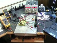
working 27W@1KHz into 12 ohm load!
If anyone is interested, I have built one channel and one power supply, all per
Nelson's design (to the best of my ability). I have connected everything, and
done a little testing (which is about all I know how to do).
With a 1KHz triangle wave, I get 27W into 12 ohms (I don't have any 8 ohm
power resistors), with 3.8V input. I also looked at some square waves up to
20KHz. There is a little bit of corner rounding at 20Khz, but no overshoot or
ringing. This is a "test" setup, with long leads going to the transistors. Not
that things are bad or anything, but I think the 20KHz corners will get even
better when I mount things "for real" and have shorter leads.
Anyway, it sounded well enough for me to build the second channel, and
some mono boxes. More pictures soon.
Attachments
AndrewT said:Hi,
is that 8 readouts I see before me?
The eyes of a fly to take in all that info at once.
Can anyone instruct us how we can use a PC to collect all this info in just a few mS and then peruse the data at our leisure?
HI AndrewT,
Well, aside from the VM's and such, I use a PC/USB based O-scope. It is
made by EasySync Ltd, which is in the UK, I think. The model I use is a
DS1M12 Stingray. I think it can do at least 250KHz and 50VDC. I am a
CS guy, not a EE (, so I don't know much about scopes), but I think this is
on the slow (very slow?) side of conventional scopes. However, it is PC
based, and can capture data, as you asked...
Maybe I'll be able to post some pics of traces from the PC based scope
after I get this thing into a box. I'm not sure how big the pics of traces are,
but I know we have a posting limit of 1MB. So, no promises...
-- Robert
Hi Audiorob,
your PC scope will get you by. But it will miss out a lot of important information, either due to too infrequent sampling or due to software smoothing over the data to generate the pics to be displayed.
Buy yourself a real, non digital, scope about 20MHz to 50MHz for audio testing.
Traditionally, a digital scope needed a sampling frequency of about 10 times the maximum display frequency to achieve accuracy and resolution. I am told that modern digital scopes can do a lot better than this.
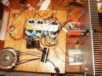
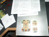
Pics of main and PS boards
Here is a pic of the main board and the small boards for the power supply circuit.
They are sitting on one of the heat sinks. The heat sinks for the main transistors
are 12"x19.5", but I think they need to be a little be bigger.
Although it is not shown, the main board is mounted in the center of the heatsink
with the transistors wired to the green terminal blocks. With about 2 inch leads,
the transistors are mounted on the heatsink with equally spacing. The front of the
board (with the POTS) then faces the top (or bottom) of the heatsink, so the
POTS are fairly easy to reach. Note that both POTS are on the same side of
the board so that I don't have to move very far to make adjustments.
You might be able to see that the caps on the main board are not an exotic brand.
Does anyone know if, say Black Gate caps would really make a difference? I
think the BG caps are about $2.50 each, but I haven't tried them because there
are minimum orders... Also, I have no idea what Nelson means when he mentions
bypass caps, so if they make a difference, and if anyone would like to enlighten
me, I need some schooling.
On the other hand, I have learned a lot from doing this project. And it has been
a lot of fun! Pics of the amps in boxes soon...
-- Robert
Attachments
Re: Pics of main and PS boards
The reason we are using plastic film (polyester, polypropylen) bypass caps across electrolytic caps is that the electrolytic caps becomes more inductive with higher frequencies. Placing a film cap (1uF is a good value) across the electrolytic lets the higher frequencies bypass the electrolytic via the film cap.
Conclusion: Much better sound in the mid/high frequencies. Some people actually likes the more romantic sound you get from not bypassing the el.cap. Using a tantalum electrolytic makes the sound even more "romantic".
audiorob said:H I
think the BG caps are about $2.50 each, but I haven't tried them because there
are minimum orders... Also, I have no idea what Nelson means when he mentions
bypass caps, so if they make a difference, and if anyone would like to enlighten
me, I need some schooling.
The reason we are using plastic film (polyester, polypropylen) bypass caps across electrolytic caps is that the electrolytic caps becomes more inductive with higher frequencies. Placing a film cap (1uF is a good value) across the electrolytic lets the higher frequencies bypass the electrolytic via the film cap.
Conclusion: Much better sound in the mid/high frequencies. Some people actually likes the more romantic sound you get from not bypassing the el.cap. Using a tantalum electrolytic makes the sound even more "romantic".
Re: Pics of main and PS boards
first-AVOID terminal blocks for any semiconductor,especially output transistors;just solder them
second- bypass caps are small ones ,soldered in parallel to bigger ones;they are ,presumably, there to speed up things (ya know-mambo jumbo about parasitic inductivity in large caps etc) ;in some cases there is benefit in bypassing,in some other cases isn't ;
your ears will decide ;try with some 1uF bypass film caps,then decide what you like.
audiorob said:Here is a pic of the main board and the small boards for the power supply circuit.
They are sitting on one of the heat sinks. The heat sinks for the main transistors
are 12"x19.5", but I think they need to be a little be bigger.
Although it is not shown, the main board is mounted in the center of the heatsink
with the transistors wired to the green terminal blocks. With about 2 inch leads,
the transistors are mounted on the heatsink with equally spacing. The front of the
board (with the POTS) then faces the top (or bottom) of the heatsink, so the
POTS are fairly easy to reach. Note that both POTS are on the same side of
the board so that I don't have to move very far to make adjustments.
You might be able to see that the caps on the main board are not an exotic brand.
Does anyone know if, say Black Gate caps would really make a difference? I
think the BG caps are about $2.50 each, but I haven't tried them because there
are minimum orders... Also, I have no idea what Nelson means when he mentions
bypass caps, so if they make a difference, and if anyone would like to enlighten
me, I need some schooling.
On the other hand, I have learned a lot from doing this project. And it has been
a lot of fun! Pics of the amps in boxes soon...
-- Robert
first-AVOID terminal blocks for any semiconductor,especially output transistors;just solder them
second- bypass caps are small ones ,soldered in parallel to bigger ones;they are ,presumably, there to speed up things (ya know-mambo jumbo about parasitic inductivity in large caps etc) ;in some cases there is benefit in bypassing,in some other cases isn't ;
your ears will decide ;try with some 1uF bypass film caps,then decide what you like.
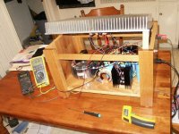
Zen 5, in a box
First, a big thanks to Mad_K and Zen Mod for the explanation and information. I
will add experimenting with the caps to my "to do" list. Thank you again!!!
Zen Mod - initially, I didn't understand the jibes about the mess (this is my first
home built amp). Now, I understand. In my case, I have a mess in about
5 different places where I work (not enough room at a single work place!). I
still have a huge mess to clear. But I'm going to listen to this thing first.
This is just a pic of me biasing one monoblock. The "bonnet" (heatsink) is up
so I can better reach the POTS and take temps.
-- Robert
First, a big thanks to Mad_K and Zen Mod for the explanation and information. I
will add experimenting with the caps to my "to do" list. Thank you again!!!
Zen Mod - initially, I didn't understand the jibes about the mess (this is my first
home built amp). Now, I understand.
In my case, I have a mess in about5 different places where I work (not enough room at a single work place!). I
still have a huge mess to clear. But I'm going to listen to this thing first.
This is just a pic of me biasing one monoblock. The "bonnet" (heatsink) is up
so I can better reach the POTS and take temps.
-- Robert
Attachments
20KHz square wave trace
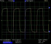
This iis a trace of a 20KHz square wave through my Zen 5 amp. I
admit that I thought that the traces would be more square, but again,
this is not my field of expertise.
Does anyone know if this is good, bad, or normal? Is there a
formalized or generally accepted method of performing square wave
tests? I may not have performed this test correctly. I only have the
vaguest idea of what I'm doing. For example, this trace has no load
except for the O-scope. Traces into an 8 ohm load look far worse,
but that is true when applying the signal through the resistor alone
(no amp, just the resistor).
Assuming I have done this correctly, I wonder if this would improve with
the bypass caps. Does anyone know?
BTW, this trace is from the USB/PC based scope mentioned in previous
posts.
Thanks,
Robert
Attachments
measuring wattage
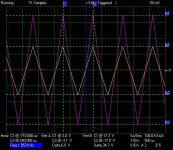
Here is another trace, this time using 1KHz triangle waves, just before the
amp clips. The yellow trace is the input. The magenta trace is the amplifier
output connected to an 8 ohm resistor load.
So, do we call this a 6V input or a 3V input?
The amp is swinging +/- 17V. If wattage is VA, then we need to know
A. From the equation V=IR, we know V and R. I'm guessing that we use
V=17 and not V=34. So:
17V = I * 8 ohms
17V/8 ohms = I
2.125 Amps = I
Then using W=VA we have:
W = 17V * 2.125 Amps
W = 36.125
Does this sound about right to everyone? (I have to ask because *I* would
have said that V should have been 34. But using that value in the equations
yeilds 4.25A and 144.5 Watts, which seems unreasonable.)
Does that look right?
thanks,
Robert
Attachments
looks good enough to me,taking in account that you have pretty crappy 'scope
find attached one pdf ,author can be known from file properties-it's bergerons ;
look for caps named C102 ,C104,C105
102 and 105 are there for stability reasons,and 104 is there to shape your rectangle waves.........
btw-I like that future case for your amp
find attached one pdf ,author can be known from file properties-it's bergerons ;
look for caps named C102 ,C104,C105
102 and 105 are there for stability reasons,and 104 is there to shape your rectangle waves.........
btw-I like that future case for your amp
Attachments
Re: measuring wattage
Not likely.
To get W RMS you need to divide your answer (36W) by 2. So yes, it is correct (18W RMS)
audiorob said:
Assuming I have done this correctly, I wonder if this would improve with
the bypass caps. Does anyone know?
Not likely.
audiorob said:
The amp is swinging +/- 17V. If wattage is VA, then we need to know
A. From the equation V=IR, we know V and R. I'm guessing that we use
V=17 and not V=34. So:
17V = I * 8 ohms
17V/8 ohms = I
2.125 Amps = I
Then using W=VA we have:
W = 17V * 2.125 Amps
W = 36.125
Does this sound about right to everyone? (I have to ask because *I* would
have said that V should have been 34. But using that value in the equations
yeilds 4.25A and 144.5 Watts, which seems unreasonable.)
Does that look right?
thanks,
Robert
To get W RMS you need to divide your answer (36W) by 2. So yes, it is correct (18W RMS)
Hi,
when defining your triangle wave you can use peak to peak (Vpp) or just the ref to peak voltage (Vpk). If it was asymetrical you would define the DC offset as well.
Peak power into a load using sinewave signal is P = Vpk^2 / R = Ipk^2 * R = Vpk * I. All three give the same answer. Use the version for which you know the operands.
The power is the peak power divided by two, P = Ppk / 2 = Vpk^2 / 2R.
Your DMM reads rms (AC average) when doing these measurements.
In this case the power using rms measurements is P = Vac^2 / R, omitting the divide by two.
- Status
- This old topic is closed. If you want to reopen this topic, contact a moderator using the "Report Post" button.
- Home
- Amplifiers
- Pass Labs
- problems building zen 5 amp