Schematic, (standart Loftin - White schematic):
here
Amplifier - early version, input stage with double triode 6N3P in paralel (without power supply module):
Gallery of Bulgarian Audiophile Society
Input stage - russian single triode 6S3P-EV
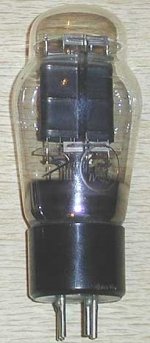
Output triode - 6A3/6B4G/6S4S; 2A3/2S4S (with 2.5V heating)
Kenotron - russian 5C4S(EZ81 with 6.3V h.v.)
bypass el. capacitors - russian silver-tantalum, military production.
Geometry of used core in attachment.
here
Amplifier - early version, input stage with double triode 6N3P in paralel (without power supply module):
Gallery of Bulgarian Audiophile Society
Input stage - russian single triode 6S3P-EV
Output triode - 6A3/6B4G/6S4S; 2A3/2S4S (with 2.5V heating)
Kenotron - russian 5C4S(EZ81 with 6.3V h.v.)
bypass el. capacitors - russian silver-tantalum, military production.
Geometry of used core in attachment.
Attachments
The project was "slightly" modified ")
Here is the last version:
http://www.geocities.com/dreamsdestroyer/6C4C_cap.gif
Here is the last version:
http://www.geocities.com/dreamsdestroyer/6C4C_cap.gif
Yes, 17 watts is more than the absolute maximum... Ua max=360V (for 6S4S) not 300
It is a little more than recommended power dissipation, but all is OK, Anode become reddish when power dissipation is more than 21-22 watts
The sound is much "bigger" than early wersion - 250V a-c Ia=60mA
Also I changed the transformer ratio (29.63:1) and anode load (more than 3k)
It is a little more than recommended power dissipation, but all is OK, Anode become reddish when power dissipation is more than 21-22 watts
The sound is much "bigger" than early wersion - 250V a-c Ia=60mA
Also I changed the transformer ratio (29.63:1) and anode load (more than 3k)
I find the 6S4S likes lots of volts too, I run them at 350V and 50mA so very close to your point. I'm using a 5K load aand it is super. There is more delicacy in the amp at this loading than at 2.5K.
I prefer the 6S4S run like this to the 6B4Gs and 2A3 that I have tried at their recommended points.
AGree on the getting the pre 1969 6S4S too
James
I prefer the 6S4S run like this to the 6B4Gs and 2A3 that I have tried at their recommended points.
AGree on the getting the pre 1969 6S4S too
James
Yes, exactly that - a better sounding amp.
As for reducing the output power - No it doesn't as I can still swing the full current range but with greater voltage swing than a 3K load... thats a secondary benefit of the lifted Va - more voltage swing for the same current swing and a higher load with better sound...
So I get an honest 4Wrms output. Price is higher dissapation and shorter tube life - propbably only 2-3,000hours... small price for a better sounding 2A3 amp with tubes less than 20% the price of premium tubes that don't sound as good...
I should bequiet - or the price will go up!
James
James D. said:....a better sounding amp.
...output power - No it doesn't
Hello James,
please look at Fig. 13.14 (RDH4, p. 558), showing the power output and distorsions of a 45 against load:
at a load resistance of 6 x Ra the output power ist reduced to 1/2, but there is no further reduction of distorsions.
regards Andreas
Hello Andreas,
You really ought to look at the real world curves and op point given in the thread rather than just quote a text book on an unrelated case...
In other words the conditions under which the RDH statement is true are not the pertinent ones for the op points given in this thread.
The RDH conditions would apply if there was suffucent current at the op point for a lower load such as 3K to draw extra current at a voltage swing that was the maximum that a 5K load could swing before cutoff... however at the given op point the 5k load can draw the full current available from the valve before the valve hits cutoff... the whole point of a higher load at higher Va...
Note that I don't claim lower distortion from my op point and load at full power because it doesn't deliver that in this case - why? because I'm swinging a lot more volts than a 3k load can swing... so full power distortion is almost exactly the same...
You know valves are just like real life... practical experience building and testing things counts for a lot more than the ability to read a book - even a good text book like RDH4. Not that RDH4 is wrong but you need the practical experience to understand that the statements in the book are only entirely true under the conditions given in the book and are not universal truths...
As always rules and statements are for the guidance of the wise and the blind obedience of fools....
Andreas, Not that I think you are a fool but you need to look beyond the text in a text book to what is the really meant by the text.
James
Hello James,
the output power (in class A1) depends only from the plate voltage, the plate resistance and load resistance, not from the quiescent current (RDH4, p. 555).
The maximum output power condition is R load = 2 x R plate.
Increasing the quiescent current increases only the plate dissipation.
regards Andreas
Hello Daniel,
I've tried a few versions which often started out as 2A3 designs or 6B4G designs. Here are three, starting with a PP design.
It shows a 6B4G pair but I built it with 6S4S and used an 8K Ra-a output transformer. Va was 350 volts and Ia was 50mA.
I experimented with neutralising capacitors with this design but took then off the driver stage - they are still on the output stage.
Attachments
THe third one is in homage to a friend - Jonathan Noble whos designs inspired this approach. Its nice I intially op point but it is now running as per the above examples and sounding very very nice. Its more romantic than the pentode driven version but probably not quite as correct...
I intially op point but it is now running as per the above examples and sounding very very nice. Its more romantic than the pentode driven version but probably not quite as correct...Attachments
PSE 6C4C
Hello Gentlemen
I have much interest in this project!!
My respect to the wise opinions
-JamesD practice in the land
-AndreasS on the theory
I am not engineer, nor as much cofoundation as you.
My materials are, 6C4C production SV 1964
(less, also of production year 88)
and OPT James 5K, with idea to connect, the load of 8ohm, to the secondary one of 16 ohm, in an attempt to deceive and to lower the vision of Paralell SE 6C4Cs configuration to a minor Ra
about this form, itself being in a Ra, higher, than of the Spec., and more in agreement with the subject than they are trying
(for another SE, if I have the suitable OPT, 2k5, 3k5 Ra)
Great surprise!!! in your attachments
even 1º, with 6N3P-EB, in my thoughts, the pleasing SURPRISE with the possibility, to be able to use of my stock 6N3P-Dr (s) or 6N3P-E, (- EBs in the present distribution, fodder that is worse, by the year and different manufacture structure without mica additional superior, just as the Chinese),
and the last one with N2 tubes!?
I do not know, with a neon or light bulb of 75W???!
what would be the equivalent resistor in this circuit?
With its aid, and in my lack of knowledge, ......... more on the practice, that on
" very respectable " , theory!
Agreeing! , with tension and points of work, debated here! I am thankful for, any commentary and/or helps, that can give me, in my project PSE 6C4C, also, undecided, in using 6n6pi in configuration SRPP, .........
and like no? my favorite 6N1P-EB!!
and the possibility of 6H30P-Dr and - EBs,
Trying to use, solely, select tubes, of the Russian, military production,
in my stock 6S3P-DR triodes also.
Pleasing greetings,
and esuses by my Babelfish Inglish Translator
from Spain
Fernan
- Status
- This old topic is closed. If you want to reopen this topic, contact a moderator using the "Report Post" button.
- Home
- Amplifiers
- Tubes / Valves
- 6A3/6B4G/6S4S(2A3/2S4S) project