")
I am looking for about 100W RMS. I want to build an amp to use along with a sub for a powered subwoofer for my home theater system. I got the idea for using these D-transistors by looking at a Soundstream amp schematic. They are using 18 of em per channel for 800W RMS with +/-39.6 for the rails. I am new at designing but I spent the past three years fixing all types of electronics.
What do you mean by topology?
What do you mean by topology?
No offence but you clearly have a hell of a lot to learn. I would suggest you start off building a kit with good documentation, and then settle yourself down for a lot of reading.
If you want 100W RMS you will need 2 pairs of those devices per channel.
The TIP devices aren't too bad but there are better ones out there. I like Darlingtons for their ease of use and am using TIP142 and TIP147 in a design at the moment.
If you want 100W RMS you will need 2 pairs of those devices per channel.
The TIP devices aren't too bad but there are better ones out there. I like Darlingtons for their ease of use and am using TIP142 and TIP147 in a design at the moment.
I'll admit that there is a lot I need to learn. I have done reading on the subject of designing circuits. I got a few electronic books on the subject of engineering that I read constantly. I also have reverse engineered RF circuits and drawn up schematics due to lack of tech data. I don't have much experience with audio amps and when it comes to design, I just don't know where to start.
The TIP 102/107 pair are woefully inadequate for more than about 40W, the TIP 142/147 can do about 60W.
You want 100W out of a single pair of darlington devices you may want to use:
Mouser
2N6284 TRANS DARL NPN 20A 100V 160W TO3 $3.84
2N6287 TRANS DARL PNP 20A 100V 160W TO3 $3.88
second choice:
Digi-Key
MJ11015 TRANS DARL PNP 30A 120V 200W TO3 $3.65
MJ11016 TRANS DARL NPN 30A 120V 200W TO3 $3.65 (non stock)
On Semiconductor has a plastic version of the 2N6283 darlington series that may be worth a try. The old metal case devices may be hard to get these days.
I did some simulation in PSpice of amplifiers using the TIP142/147 output devices with MPSW06 and W56 in all other positions. Properly biased, I got about 0.02% THD with a single ended differential front end, and about 0.01% THD with a complementary differential front end. Harmonic distribution was not too bad, though I get better results with pure Class A designs (is anyone surprised? - I thought not...). As always, the simulations are for indicating general trends/shortening bench time, not a be-all and end-all. After all, you can't listen to a simulation. I started with a circuit out of the old Motorola power darlinton app note from circa 1973 using an extra driver stage with the emitters hooked together with a resistor. Simulated performance for the single ended differential amp was not too shabby with a 100ma output quiescent current, though the amp needed lag compensation to quell oscillation, just like in the app note... I will post some circuits if folks are interested.
I did some simulation in PSpice of amplifiers using the TIP142/147 output devices with MPSW06 and W56 in all other positions. Properly biased, I got about 0.02% THD with a single ended differential front end, and about 0.01% THD with a complementary differential front end. Harmonic distribution was not too bad, though I get better results with pure Class A designs (is anyone surprised? - I thought not...). As always, the simulations are for indicating general trends/shortening bench time, not a be-all and end-all. After all, you can't listen to a simulation. I started with a circuit out of the old Motorola power darlinton app note from circa 1973 using an extra driver stage with the emitters hooked together with a resistor. Simulated performance for the single ended differential amp was not too shabby with a 100ma output quiescent current, though the amp needed lag compensation to quell oscillation, just like in the app note... I will post some circuits if folks are interested.
It should also be pointed out that the Pass A40 board is still available for $6 from AudioXpress.com
The A40 used two pair of TO-3 darlington for 40W of class A power. With adequate heatsinking one pair will give 100W in lower bias class AB.
It should be pointed out that 1W of plastic does not equal 1W of metal when it comes to dissipation. The difference is the 150°C vs the 200°C maximum junction temperature ratings of the devices.
When pushing the minimum number of devices to their limits, the junctions are typically running around 100°C. De-rating to maximum junction temperature for the respective types shows us that it takes 2W of 150°C plastic to equal 1W of 200°C metal. This would seem to indicate that two pair of TIP142/147 are not quite equal to one pair of 2N6284/87.
It all depends upon the MTBF you are willing to accept.
100 watts amp
Hi guys, I find this schematic amplifier at http://europa.spaceports.com/~fishbake/index.html and i buid it but the tip 147 explode when use at 4 ohms and just deliver aprox. 40 watts.
Do you have any suggestion for this amp or is an horrible circuit or may be is a little joke of this guy? (I think, for example bc556 is the best option for the signal transistors).
Thank you for your help and comments
Greetings
Attachments
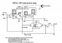
I have seen this circuit floating around here a bit. If I remember correctly, I believe it is supposed to work, it might not be the best, but it should work.
I can't see it putting out 100 or 150 watts. The device itself is rated for 125 watts. Could be an indication to why your amp blew up.
I can't see it putting out 100 or 150 watts. The device itself is rated for 125 watts. Could be an indication to why your amp blew up.
The schematic is a standard 3-stage amp paired down to the bare essentials, and not too well at that. It may be able to deliver 100W into a purely resistive load, as they say here, going down hill with the wind in it's back, for a short time. Don't expect sound quality from it, it has zero output stage bias so crossover distortion is going to be very high.
The reason why you get exploding transistors when driving a 4 ohm load, is because the ones used are woefully inadequate for the task - you simply violate the SOA curves, which in BJTs results in secondary breakdown - a fast and explosively spectacular failure on plastic cased devices.
I would strongly suggest you find a proper schematic and use proper parts... ultimately, you are going to save yourself some time and money, and learn a lot in the process.
Thank you ilimzn, you got the truth, this circuit is awful,
I want to find a circuit not too complex due I am so lonely a guitarist with no much knowledge of electronics(and english...,ja!), I build a combo guitar amp with 2 tda 7294 (2x12) and sound fine but i want to experiment another choice.
Please take a look at this other schematic that i found at http://users.swing.be/edwinpaij/ampli_mosfet_simple.htm and tell me your opinion(or anyone in this forum),if it can be work well, at least it seems to be a decent circuit, with more controls to adjust it (I don´t want to explode mosfet´s because are more expensive that the BJT´s).
Even in this page there is an upgrade version of this amp with some components but that.
Thanks to all
Attachments
It will only work with lateral mosfets. Vertical mosfets will result in thermal runaway unless you add some temperature compensation. Get rid of C5, put a cap across P2, and consider replacing P2 with a Vbe multiplier or some other temperature compensating bias generator (even if you use laterals).
I made that amp using the TIP147 and TIP142 and burnt it out but i think i figured out what was wrong. I put a 1000uf capacitor from the speaker to ground and it stopped the spark but i still need another TIP147. I emailed the guy who disigned it but he aint replying. I'll surf around a bit and see what i can find.
- Status
- This old topic is closed. If you want to reopen this topic, contact a moderator using the "Report Post" button.
- Home
- Amplifiers
- Solid State
- Tip102/tip107