(This thread contains my post from my worklog at the computer site bit-tech.net, instead of writing 2 different text's I simply copy the updateposts, and thats why there might be some minor computer words included). Hope you like my work and feel free to comment and suggest 
Okay, now its time for me to show of one of my curent projects. This is my first DIY project ever. I started the planing of my projector 1,5 years ago, and in the beggining I knew nothing about "building" or "modding". This has been my so called training project and now I'm stuck I have allready 2 new projects on the planing stage at this time. A small server and a larger HTPC case.
I Have always wanted a projector but I could never afford one. Then I came across a webpage about do it yourself projectors and decided to get started.
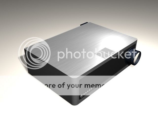
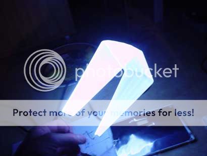
A lot of homemade projectors you see has a verry crapy and ugly look with duct tape and wood housings. This was not what I Wanted so I decided to make a projector out of aluminium and make it look as good as possible.
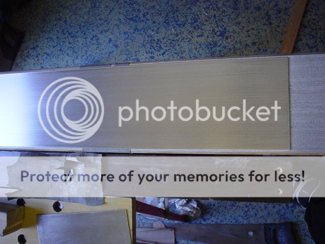
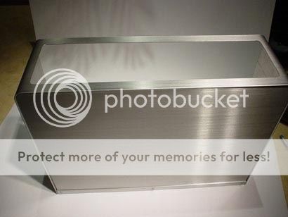
This is how I want it to look. The Alu plates will be brushed.
(click to ZOOM)
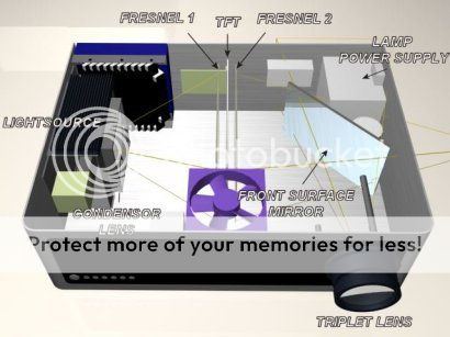
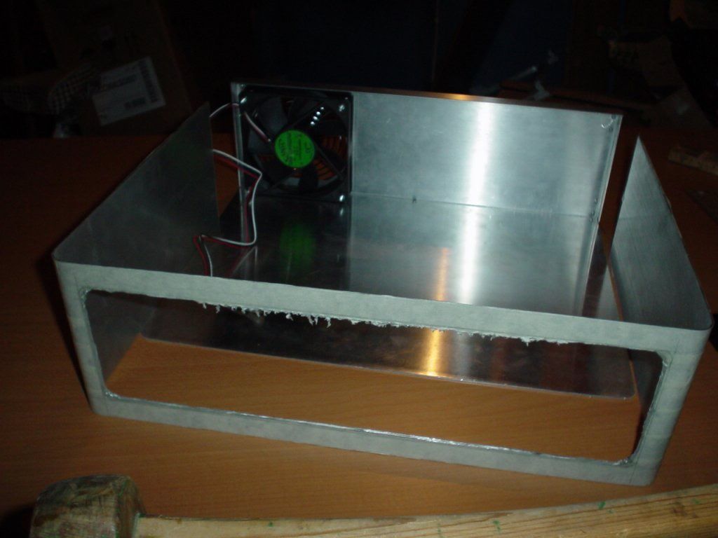
Here is the internal structure. This type of projector is similar to those overhead projectors schools and offices often use. But instead of a translucent overhead paper you use a dissassembled TFT panel. Without the backlight TFT panels are verry thin and translucent. The distances between the different lenses etc are determined by the focal lengt of each lens. Finding the right type of lenses and lamp was the hardest part for me. I live in Sweden and I tried to find all the single parts here but I gave up since I didn't find any. And I wasn't shure if the different parts I was looking for would performe well together. Instead I bought all of the components from exclusiv-online.com. A very good Site that I recomend since they are very helpfull and they shipp worldwide.
(click to ZOOM)
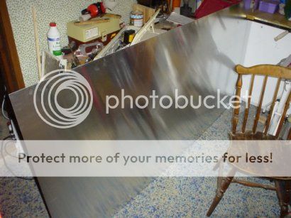
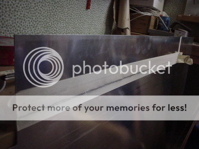
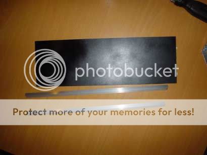
Time to get started. This was the smallest pice of 1,5mm alu tha i was allowed to order from the local metallshop. Its 2x1m
(click to ZOOM)
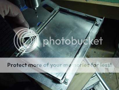
Used my dremel to cut out the bottom and backplate.
(click to ZOOM)

(click to ZOOM)
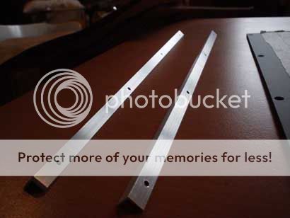
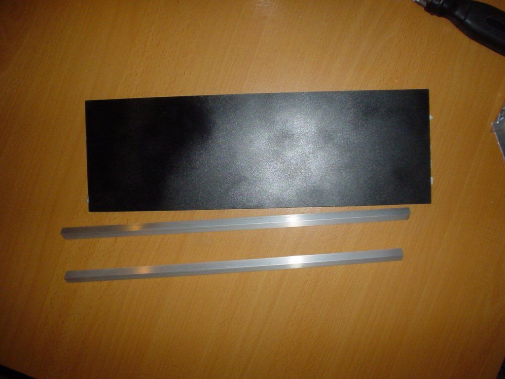
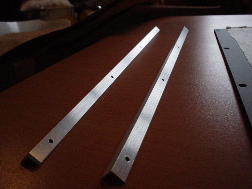
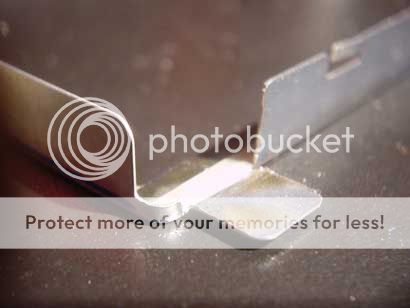
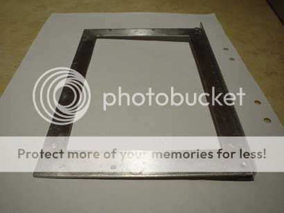
cut some alu anglebars for the backplate.
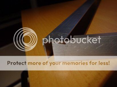
(click to ZOOM)
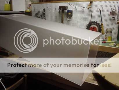
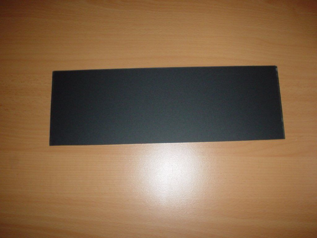
tadaa!!
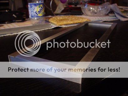
(click to ZOOM)
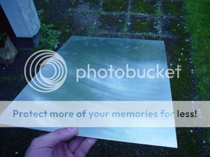
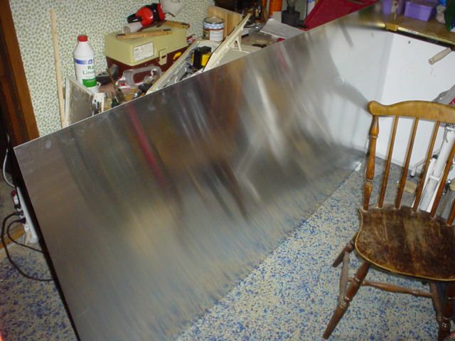
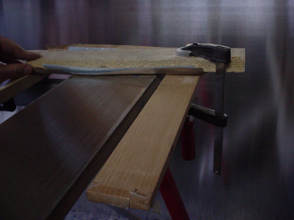
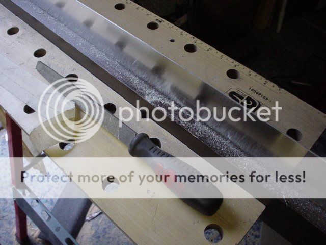
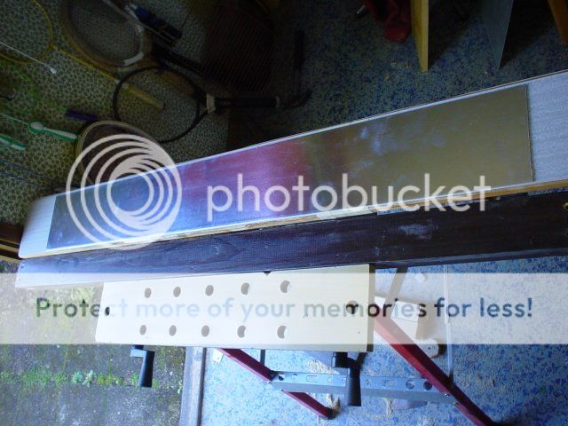
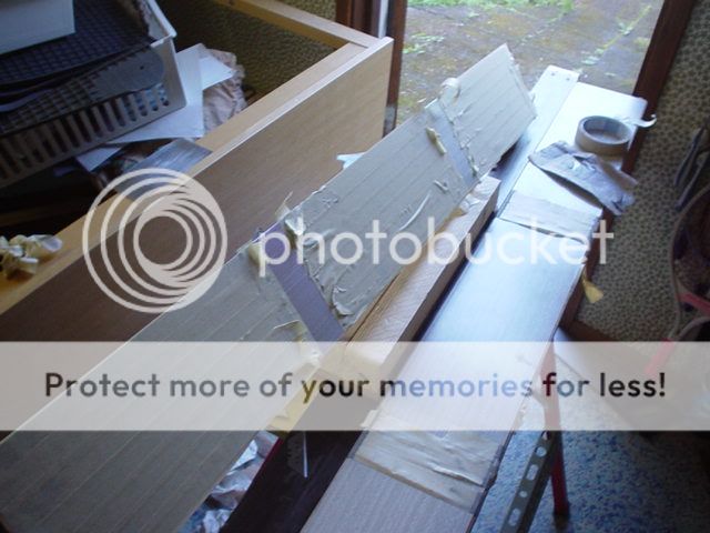
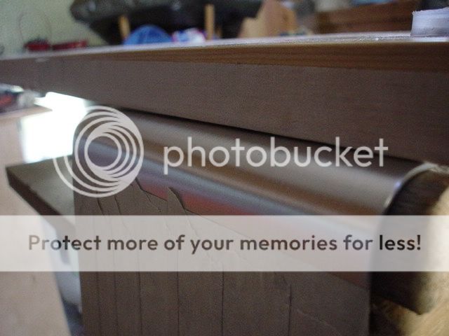
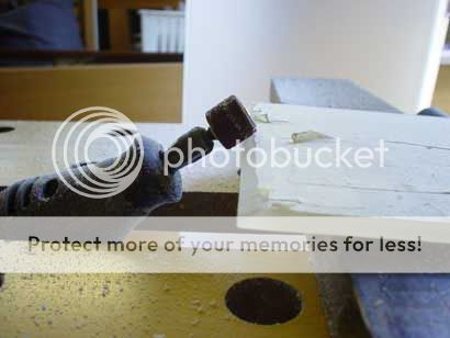
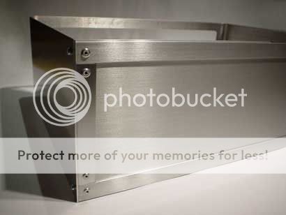
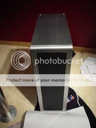
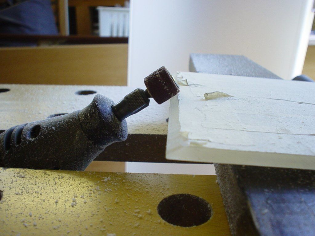
To get that that brushed alu look I used standard sandpaper. Sanding it on free hand will create a lot of scratches and the brushing wont be straight. So I created this little simple thing. The Sandpaper will stay in a straight line thanks to that support pice of wood that runs long the side of the alu plate. Between the Sandpaper and the sanding "block", there is some soft blue padding to get a soft sandingsurface to awoid some parts of the aluplate to get sanded too much. The Alu plate was taped to the work bench using double sided tape and the results turned out great.

(click to ZOOM)
almost but not yet.

(click to ZOOM)
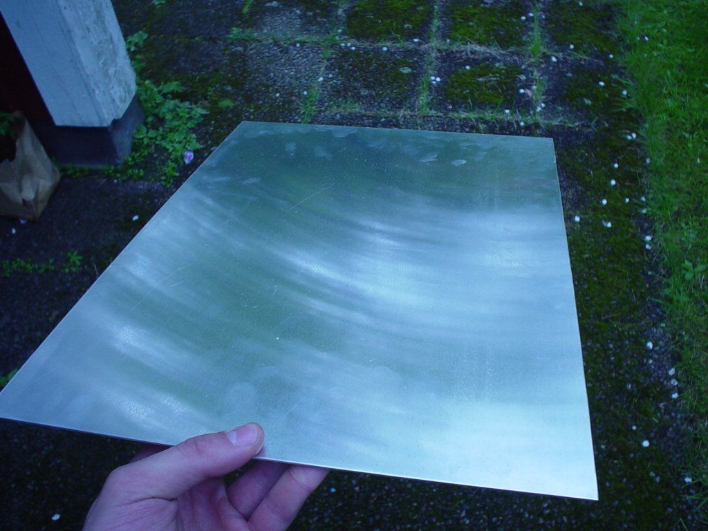
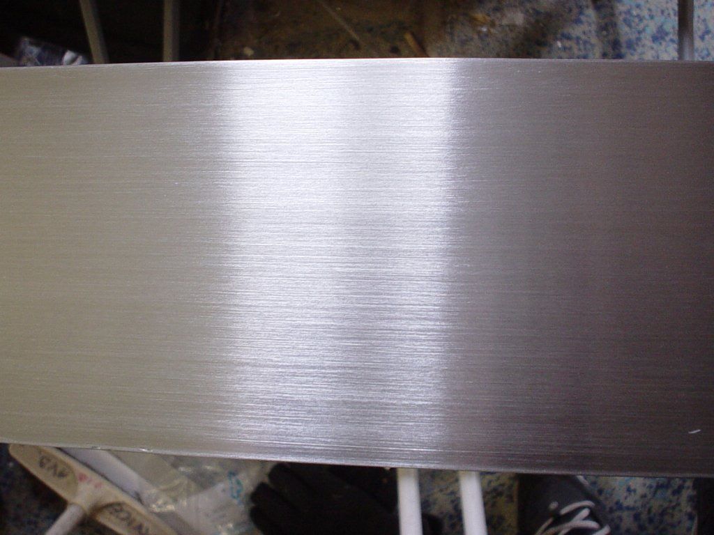
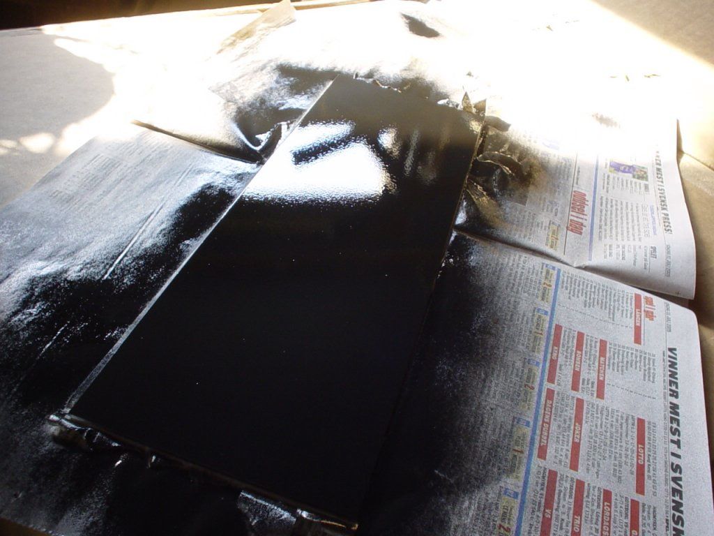
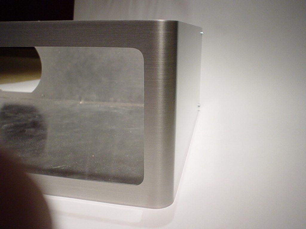
aaahh thats the look i want. But dont touch it yet those greasy fingers will make it uggly. I Used a spray can clear coat designed for alu rims, 2-4 layers, to make it greasy resistant and to give it that extra shine

(click to ZOOM)

(click to ZOOM)
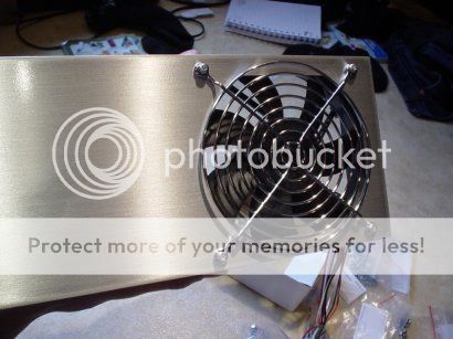
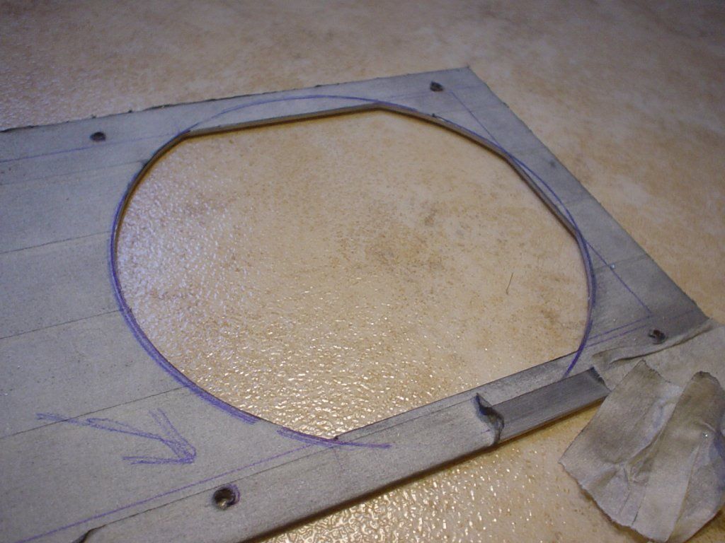
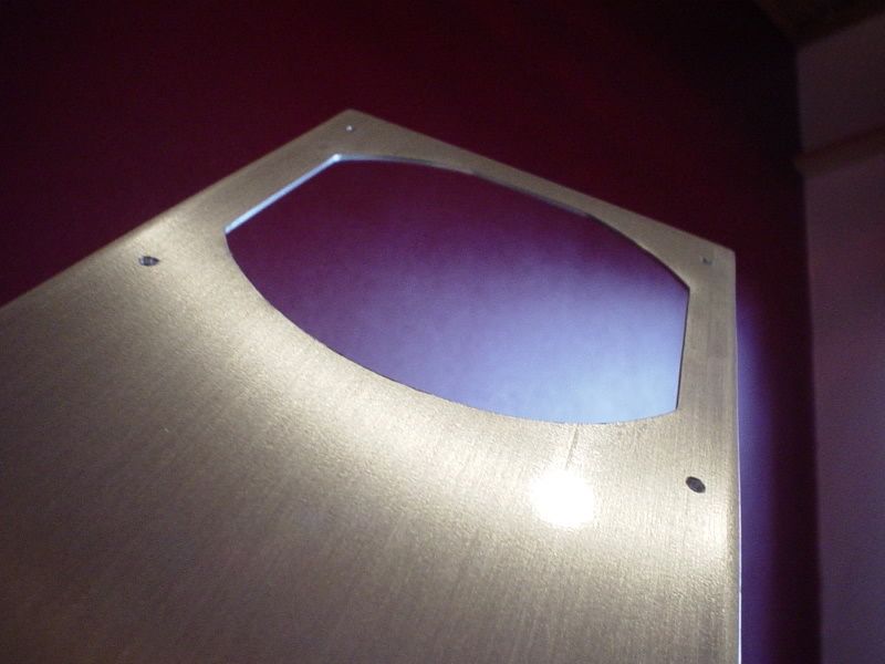
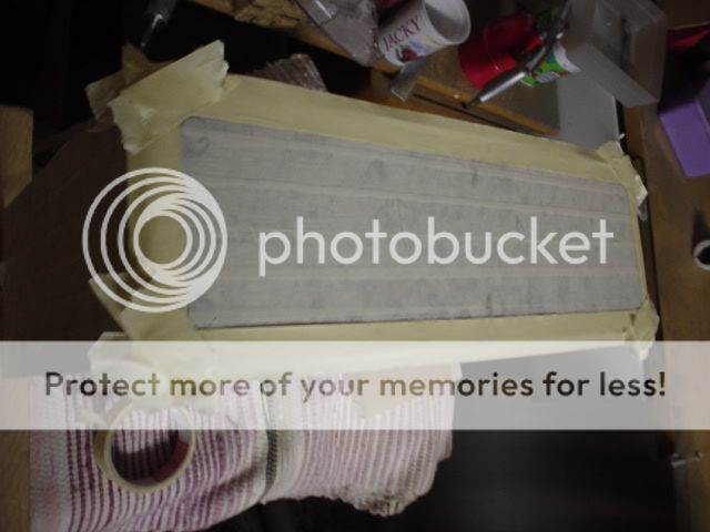
The backplate was masked and a 120mm fan hole cut.
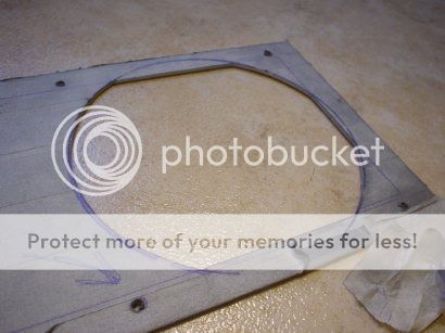
(click to ZOOM)
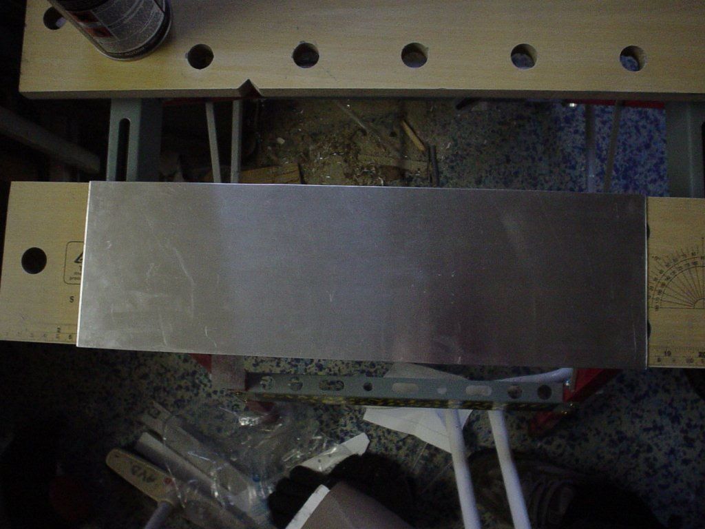
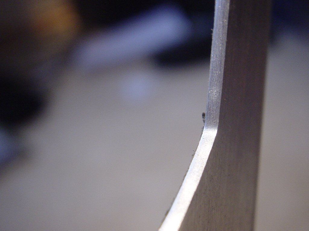
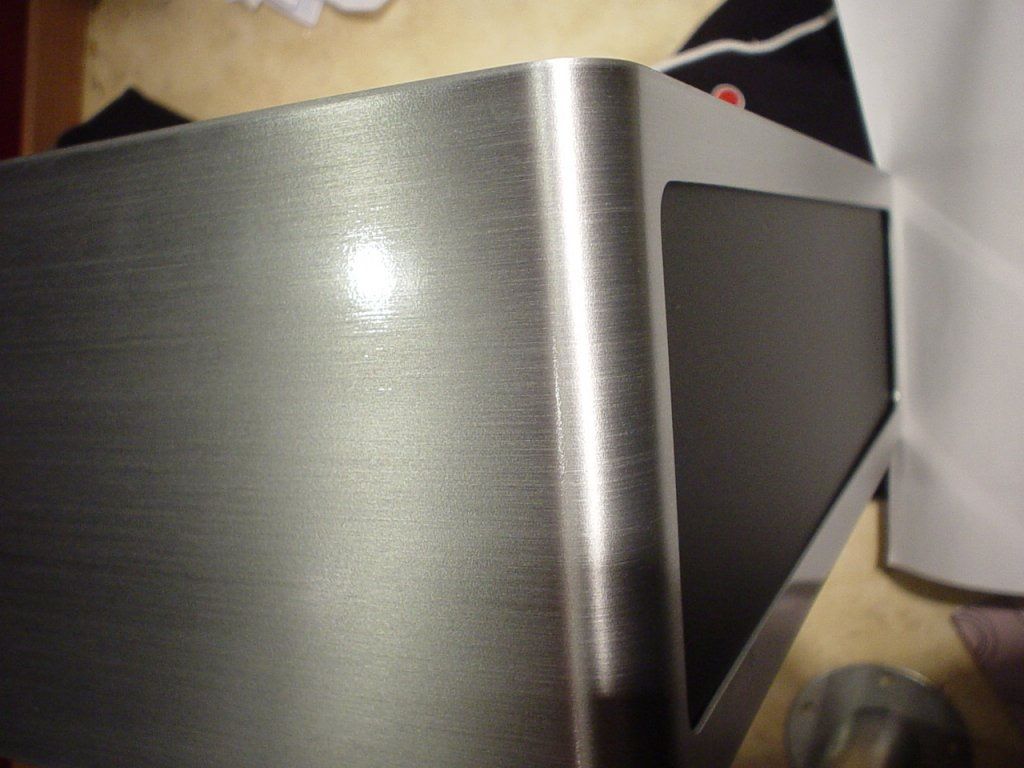
The edges where sanded using 80 , 120 , 240 grit sandpaper and is really smooth.

(click to ZOOM)

(click to ZOOM)
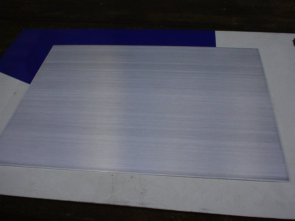
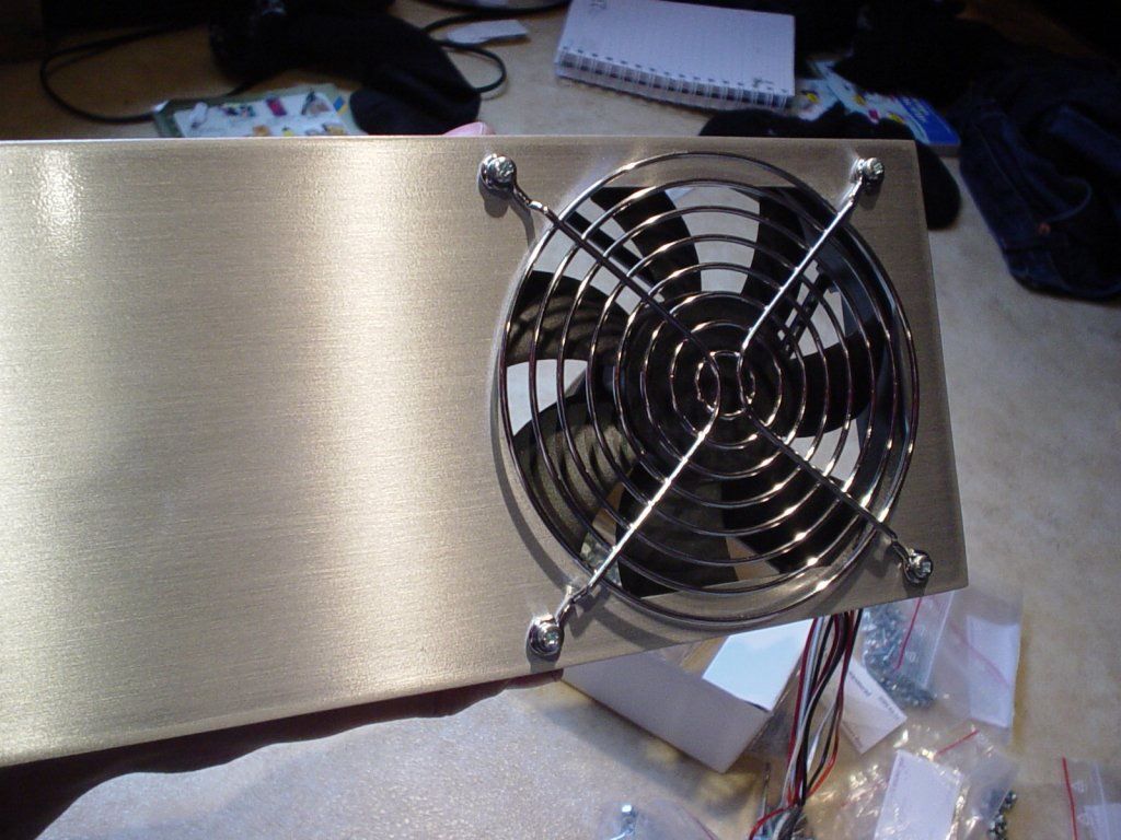
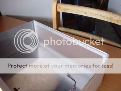
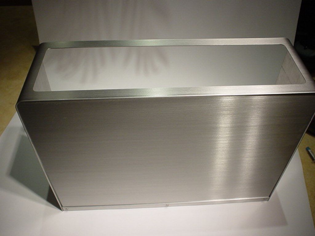
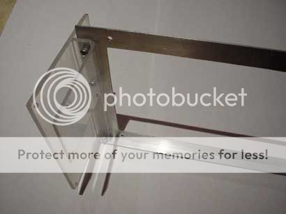
clear coated backplate testfitting
(click to ZOOM)
/GNU
Okay, now its time for me to show of one of my curent projects. This is my first DIY project ever. I started the planing of my projector 1,5 years ago, and in the beggining I knew nothing about "building" or "modding". This has been my so called training project and now I'm stuck
I have allready 2 new projects on the planing stage at this time. A small server and a larger HTPC case.I Have always wanted a projector but I could never afford one. Then I came across a webpage about do it yourself projectors and decided to get started.
A lot of homemade projectors you see has a verry crapy and ugly look with duct tape and wood housings. This was not what I Wanted so I decided to make a projector out of aluminium and make it look as good as possible.
This is how I want it to look. The Alu plates will be brushed.

(click to ZOOM)
Here is the internal structure. This type of projector is similar to those overhead projectors schools and offices often use. But instead of a translucent overhead paper you use a dissassembled TFT panel. Without the backlight TFT panels are verry thin and translucent. The distances between the different lenses etc are determined by the focal lengt of each lens. Finding the right type of lenses and lamp was the hardest part for me. I live in Sweden and I tried to find all the single parts here but I gave up since I didn't find any. And I wasn't shure if the different parts I was looking for would performe well together. Instead I bought all of the components from exclusiv-online.com. A very good Site that I recomend since they are very helpfull and they shipp worldwide.

(click to ZOOM)
Time to get started. This was the smallest pice of 1,5mm alu tha i was allowed to order from the local metallshop. Its 2x1m
(click to ZOOM)
Used my dremel to cut out the bottom and backplate.
(click to ZOOM)
(click to ZOOM)
cut some alu anglebars for the backplate.
(click to ZOOM)
tadaa!!

(click to ZOOM)
To get that that brushed alu look I used standard sandpaper. Sanding it on free hand will create a lot of scratches and the brushing wont be straight. So I created this little simple thing. The Sandpaper will stay in a straight line thanks to that support pice of wood that runs long the side of the alu plate. Between the Sandpaper and the sanding "block", there is some soft blue padding to get a soft sandingsurface to awoid some parts of the aluplate to get sanded too much. The Alu plate was taped to the work bench using double sided tape and the results turned out great.
(click to ZOOM)
almost but not yet.

(click to ZOOM)
aaahh thats the look i want. But dont touch it yet those greasy fingers will make it uggly. I Used a spray can clear coat designed for alu rims, 2-4 layers, to make it greasy resistant and to give it that extra shine
(click to ZOOM)
(click to ZOOM)
The backplate was masked and a 120mm fan hole cut.
(click to ZOOM)
The edges where sanded using 80 , 120 , 240 grit sandpaper and is really smooth.
(click to ZOOM)
(click to ZOOM)
clear coated backplate testfitting
(click to ZOOM)
/GNU
Time for some more pics.
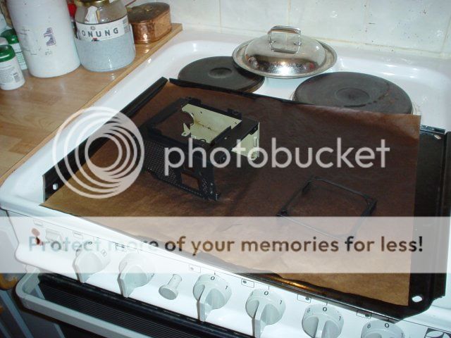
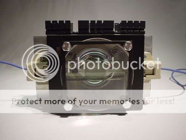
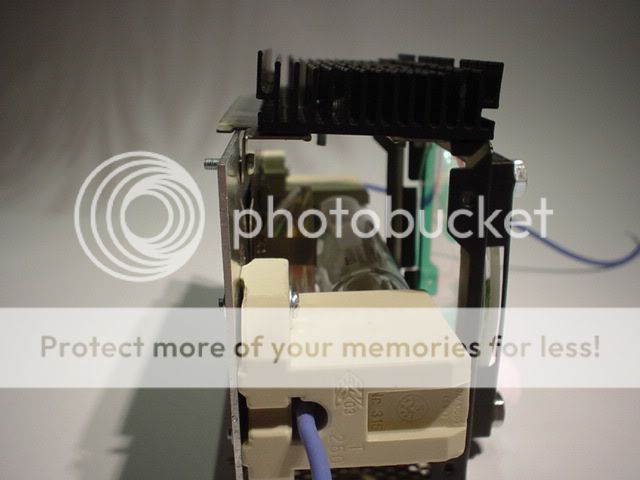
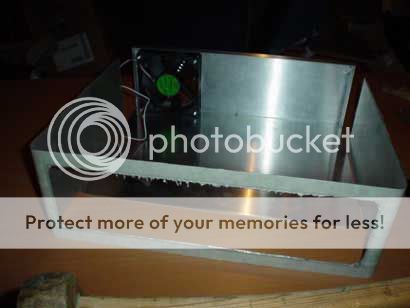
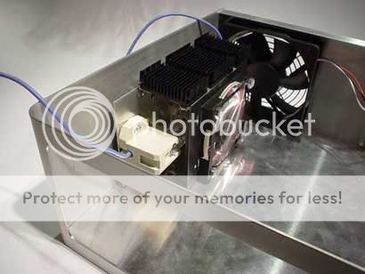
Here is the lamp housing. It's made out of an old m-atx PSU.
The fanguard is cut away and holes are cut on each side to fit the condensorlens and the IR-filter.
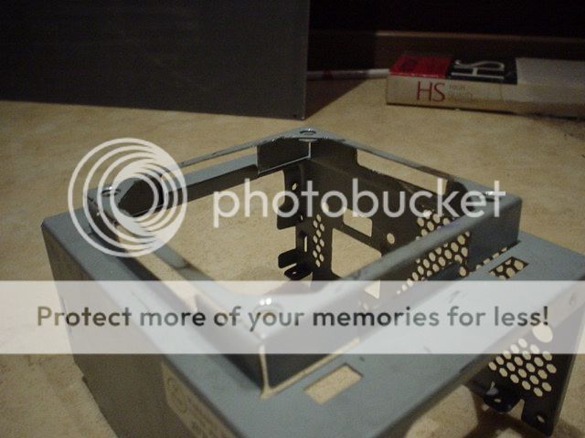
testfitting the condensor lens.
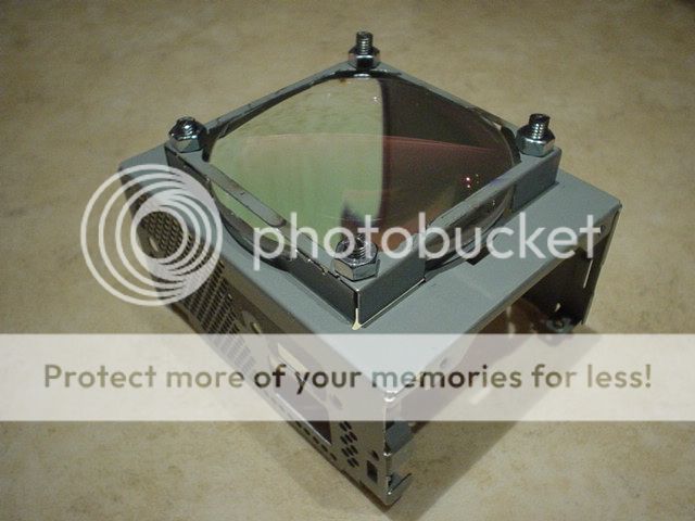
the lamp housing is painted using heat resistant 600 C engin paint. To make it cure it needs to be heated slow to 225 C. This was probably not needed in my case but I gave it a try. So I put it in the owen And it turned out well. It looks and feels like black anodized aluminium
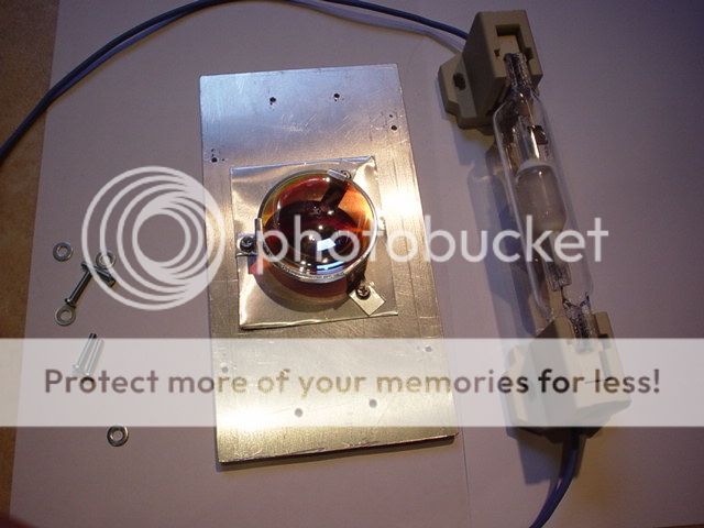
Here you can se the conensor lens on top and the IR-Filter on the bottom. The IR-filter is for removing some of the heat from the light directed forward. This will make the tft run a little bit cooler.

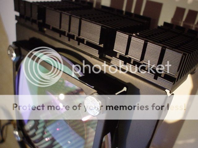
The lamp and the lamp attacment with a reflector.
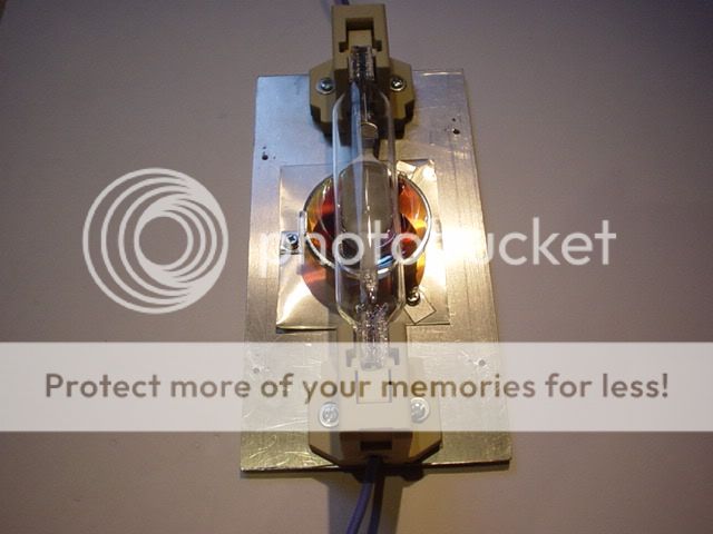
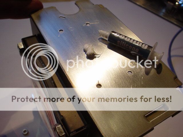
I used wet sanding paper to smoothen the surface where the Heatsink will be. Put some thermal paste on and attached the heatsink with M3 screws/nuts.
Done!
Here is the lamp housing. It's made out of an old m-atx PSU.
The fanguard is cut away and holes are cut on each side to fit the condensorlens and the IR-filter.
testfitting the condensor lens.
the lamp housing is painted using heat resistant 600 C engin paint. To make it cure it needs to be heated slow to 225 C. This was probably not needed in my case but I gave it a try. So I put it in the owen And it turned out well. It looks and feels like black anodized aluminium
Here you can se the conensor lens on top and the IR-Filter on the bottom. The IR-filter is for removing some of the heat from the light directed forward. This will make the tft run a little bit cooler.
The lamp and the lamp attacment with a reflector.
I used wet sanding paper to smoothen the surface where the Heatsink will be. Put some thermal paste on and attached the heatsink with M3 screws/nuts.
Done!
So...here are the new pictures showing the fabrication of the left-front-right wall(s) of the projector case.
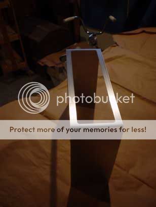
All three parts will be constructed from one big pice. Its cut out from the same aluminium plate as the bottom and back plate, using a dremel. I had to use a lot of "cheap" cutting disks because I was out of my original Dremel cutting disks.
I attached the plate to the workbench with some support wood (the dark ones) to get a larger "clamp" surface and avoid bending and misshaping the alu plate.To get the perfect size and nice edges, I used a normal file..??(i think thats what it's called in english) And some 120 , 240 grit sandpaper to get a smooth edge.
The plate is attached to the bench with double sided tape and brushed using the same method as mentioned earlier.
Time to bend. The whole plate is masked exept the parts that will be bent.
to get a smooth and round bend, I use a piece of old broomstick attached to a piece of wood. I clamp the whole structure to the work bench and use another piece of wood to apply even pressure and bend the whole thing
Voila!!
I used the rest of the broomstick to bend the plate a little bit more ,like this to make shure the angle was 90 degrees as the plate was flexing back after the first method.
front
The front is masked and ready for the giant hole to be cut out.
I used a lot of protecting maskin tape as I know that sometimes the Cutting disk might slip away and if that happens 1 layer of masking tape won't do the trick.... but 4 layers will do better safe than sorry.
All three parts will be constructed from one big pice. Its cut out from the same aluminium plate as the bottom and back plate, using a dremel. I had to use a lot of "cheap" cutting disks because I was out of my original Dremel cutting disks.
An externally hosted image should be here but it was not working when we last tested it.
I attached the plate to the workbench with some support wood (the dark ones) to get a larger "clamp" surface and avoid bending and misshaping the alu plate.To get the perfect size and nice edges, I used a normal file..??(i think thats what it's called in english) And some 120 , 240 grit sandpaper to get a smooth edge.
An externally hosted image should be here but it was not working when we last tested it.
The plate is attached to the bench with double sided tape and brushed using the same method as mentioned earlier.
An externally hosted image should be here but it was not working when we last tested it.
An externally hosted image should be here but it was not working when we last tested it.
Time to bend. The whole plate is masked exept the parts that will be bent.
An externally hosted image should be here but it was not working when we last tested it.
to get a smooth and round bend, I use a piece of old broomstick attached to a piece of wood. I clamp the whole structure to the work bench and use another piece of wood to apply even pressure and bend the whole thing
An externally hosted image should be here but it was not working when we last tested it.
Voila!!
An externally hosted image should be here but it was not working when we last tested it.
An externally hosted image should be here but it was not working when we last tested it.
I used the rest of the broomstick to bend the plate a little bit more ,like this to make shure the angle was 90 degrees as the plate was flexing back after the first method.
An externally hosted image should be here but it was not working when we last tested it.
An externally hosted image should be here but it was not working when we last tested it.
front
An externally hosted image should be here but it was not working when we last tested it.
The front is masked and ready for the giant hole to be cut out.
An externally hosted image should be here but it was not working when we last tested it.
I used a lot of protecting maskin tape as I know that sometimes the Cutting disk might slip away and if that happens 1 layer of masking tape won't do the trick.... but 4 layers will do better safe than sorry.
An externally hosted image should be here but it was not working when we last tested it.
julius20 said:Hi the_gnu,
very very nice work. Did you make this brush - style or did you buy it already looking this way...? If you make it, how do you do this??
Greetings Arno
Thanks a lot...I made the brushing myself.. I show how in the first post. It was very easy, just using the tools laying around. You can find a more detailed guide I made on
http://forums.bit-tech.net/showthread.php?t=114028 but it is the same method as mentioned in the first post
nick[x1] said:Looking very good so far!
Not too sure about your light box though!
THx... The ligtbox isnt optimal I know that, dont know if the heatsink is doing any good etc.. But the reflektor, lamp and lenses are almost on the exakt distance from eachother that is recomended at exclusiv-online.com. What were you thinking of?.. anything I can improve.??
Time for some more pics of the projector case assembly.
CLICK images for larger pictures
the cutt is finished with a file and 240 grit sandpaper to get a perfectly smooth edge.
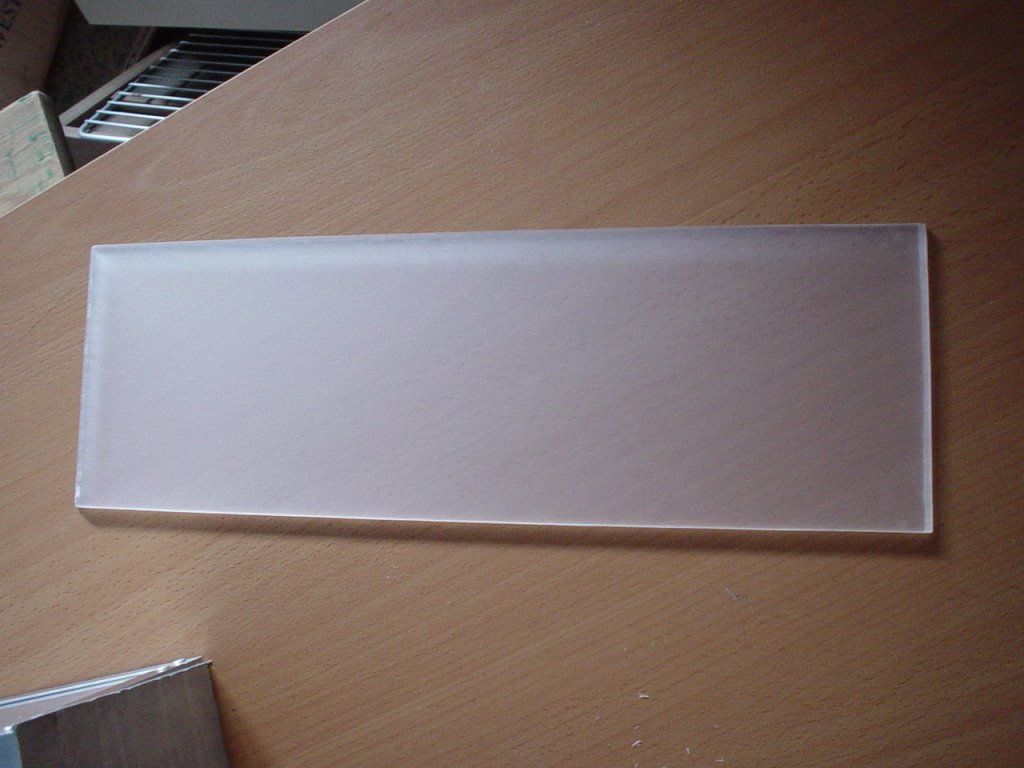
I will use a big piece of frostet plexi in that big hole. I will paint it black to prevent any light leaks. This is the plexi I am using. I got it from my temporary work at a drugstore. They where in the middle of moving the whole store and they had a lot of plexi that was about to be thrown away. So I got it This big piece of frosted plexi is actually a commercial stand for women make up.
Here is some of the other plexi I got for free. Take this amount x3...couldn't fit everything in the picture.

easy way to get nice edges quick without extra tools.
The piece of frosted plexi is spray painted black using heat resistant engine paint. The heat resistance isn't needed, it was just te only black paint I had and I liked the smooth and thick layer it creates.

Here you can se how it looks from the other side, the one that will be vissible.

This is the painted side of the plexi....two alu bars where cut and drilled. These will be the support for the plexi plate.
never min the finger ...please :wallbash:

test fitting the lamp
you probaby wonder where all the screws and nuts are that will hold this together. They are not there yet, this is just a test fitting and support brackets will be added later. But I will try to keep the screws as stealthed as possible.

I am going to create computer cases with the same theme....think it would be cool. I got the idea when I took this last pic.
Much more to come.... /GNU
CLICK images for larger pictures
the cutt is finished with a file and 240 grit sandpaper to get a perfectly smooth edge.

I will use a big piece of frostet plexi in that big hole. I will paint it black to prevent any light leaks. This is the plexi I am using. I got it from my temporary work at a drugstore. They where in the middle of moving the whole store and they had a lot of plexi that was about to be thrown away. So I got it
This big piece of frosted plexi is actually a commercial stand for women make up.
Here is some of the other plexi I got for free. Take this amount x3...couldn't fit everything in the picture.

easy way to get nice edges quick without extra tools.

The piece of frosted plexi is spray painted black using heat resistant engine paint. The heat resistance isn't needed, it was just te only black paint I had and I liked the smooth and thick layer it creates.
Here you can se how it looks from the other side, the one that will be vissible.
This is the painted side of the plexi....two alu bars where cut and drilled. These will be the support for the plexi plate.

never min the finger ...please :wallbash:
test fitting the lamp

you probaby wonder where all the screws and nuts are that will hold this together. They are not there yet, this is just a test fitting and support brackets will be added later. But I will try to keep the screws as stealthed as possible.
I am going to create computer cases with the same theme....think it would be cool. I got the idea when I took this last pic.
Much more to come.... /GNU
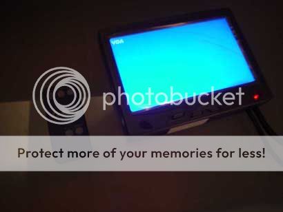
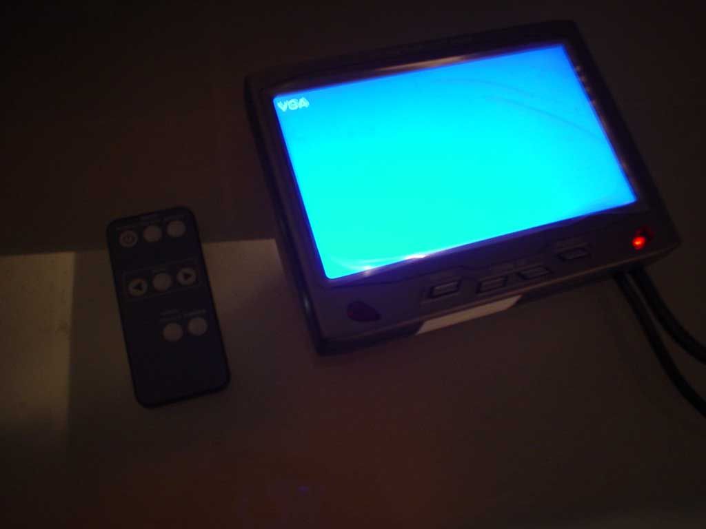
Time for some pictures of the 7" TFT and the TFT holder.
The native resolution is 800x480 but it is able to handle 1280x1024 interpolated. That means that the pixels are 800x480 but compared to normal TFT displays you can use a resolution higer than that. With hig resolutions like 1280x1024 you get a slight blur , but it works great with 1024x768. All the text on a web browser is readable.
Further data:
- PAL/NTSC standard (SECAM is not supported)
- 400 nits translucences !
- 200:1 contrast !
- 30 ms response time !
- 12 V input - 1000 mA
- Widescreen format
- over OnScreen display adjustable (AV1/2 and VGA)
The response time is claimed to be 30 ms. That normaly means a slight ghosting but I can't see any ghosting what so ever. Ben playing Counter-strike source , car games , and watched Fast motion action movies and I can't se any noticable ghosting. Hard to see any differense compared to my BENQ-FP567s with 16ms.
More pictures of the display in action
(CLICK TO ZOOM)
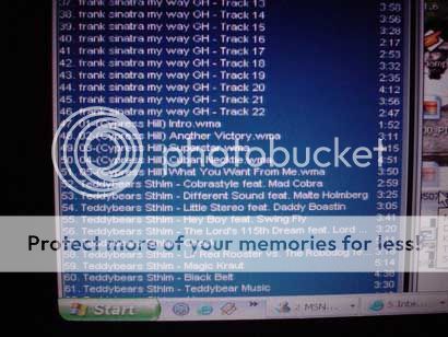
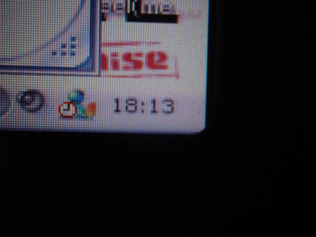
This is a closeup pic of the startmeny corner and the winamp playlist. The resolution is 1024x768. No comments on the music please.....i know zoom in on the pic to se the pixels more clearly.
(CLICK TO ZOOM)
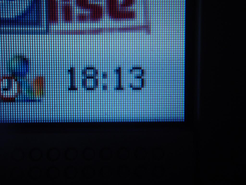
This is also a 1024x768 resolution picture. Here you can clearly se the pixelsize. Note!! that the rounded edges is only the front plastic of the TFT display.. When these are removed the whole edge will be vissible.

(CLICK TO ZOOM)
..the same picture and resolution on my 15" tft BENQ-FP567s.

(CLICK TO ZOOM)
(CLICK TO ZOOM)
(CLICK TO ZOOM)
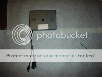
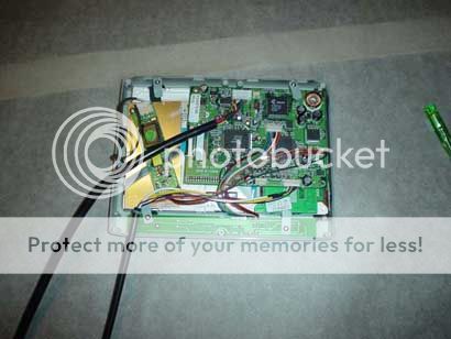
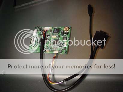
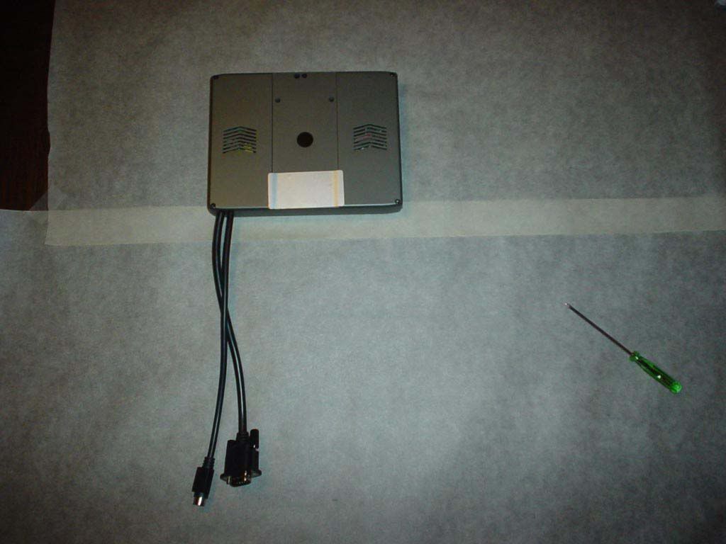
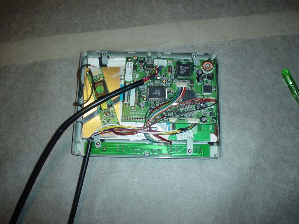
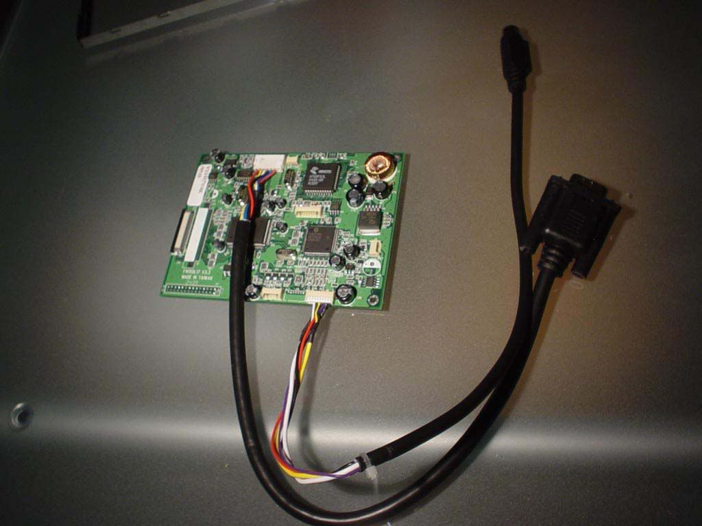
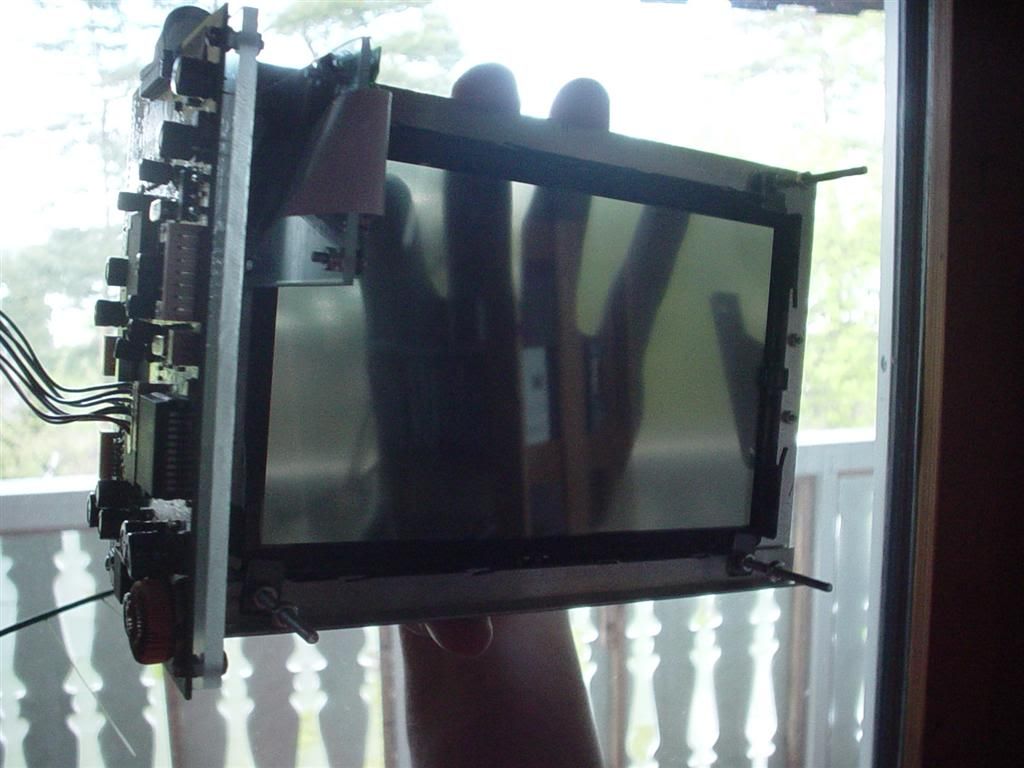
This is the controller card for the TFT.
(CLICK TO ZOOM)
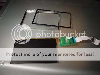
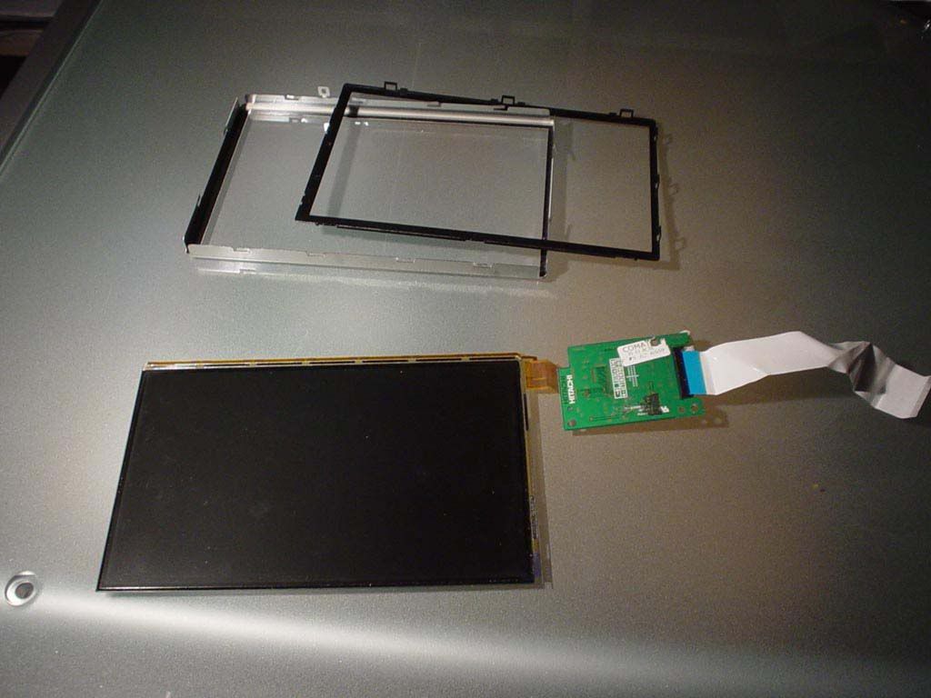
..and this is the TFT display itself. As you can see it is very thin, and you have to handle it with care to not damage those very thin brown "cables". Above the display you can see the mounting bracket that the tft was attached to.
(CLICK TO ZOOM)
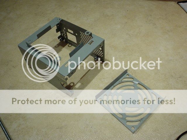
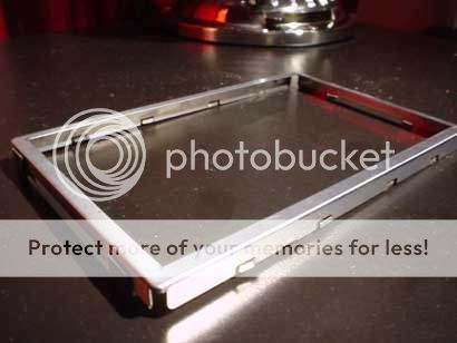
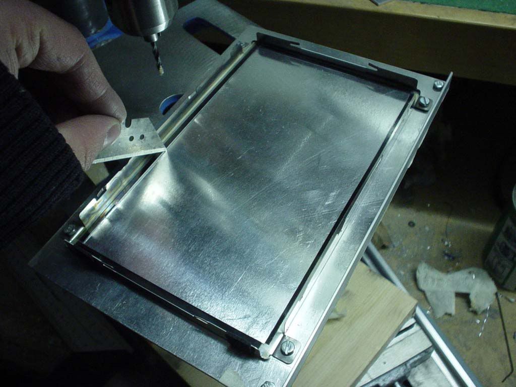
The mounting bracket again, but i need to moddify it a little bit to be abble to create my TFT holder.
(CLICK TO ZOOM)
Made 1 cut with the dremel and bendt a little piece of the frame.
(CLICK TO ZOOM)
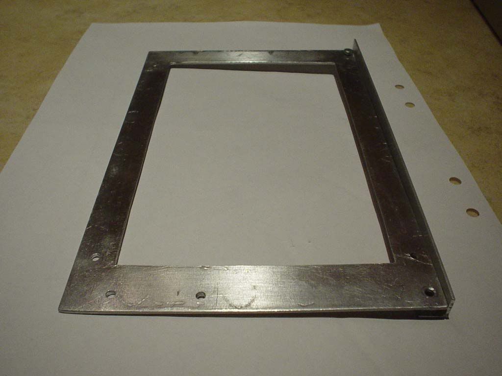
This was made in each corner and holes where drilled.

(CLICK TO ZOOM)
..attached to the mainframe and marking out where to cut.
(CLICK TO ZOOM)
(CLICK TO ZOOM)
Here you can se the controllercard supports. One for the larger one and one for the smaller. It is made out of some of the plexi I got for free. These parts are from document holder so I didn't need do create the bends by myself. was just lucky
(CLICK TO ZOOM)

(CLICK TO ZOOM)
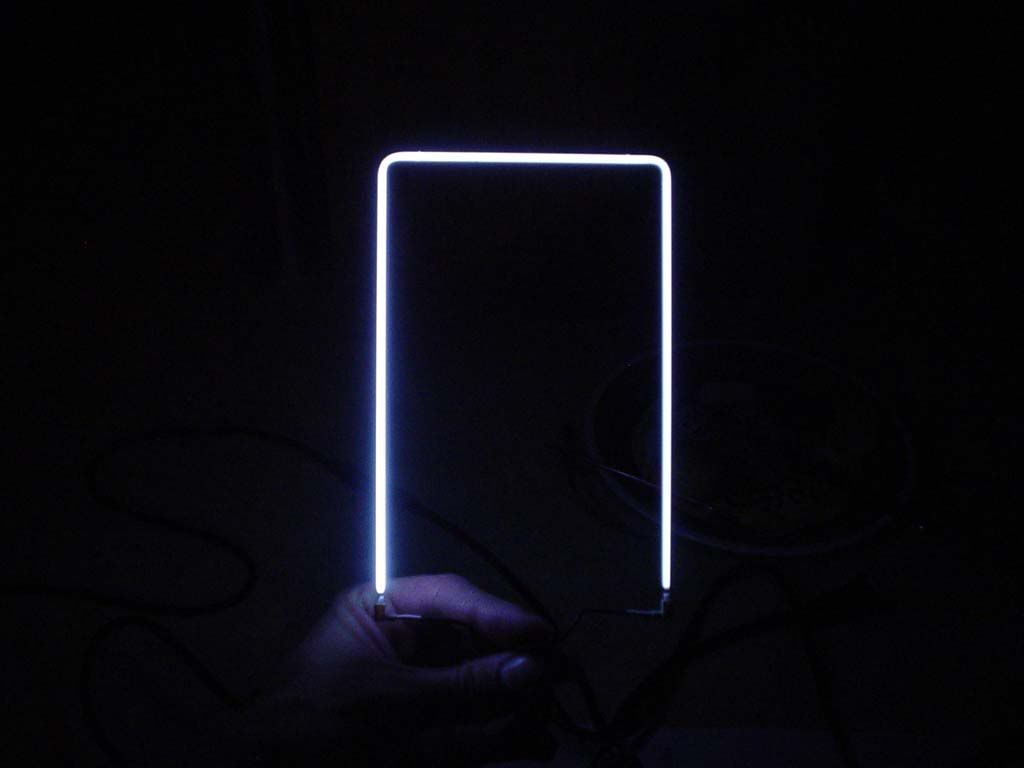
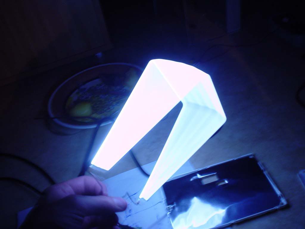
a little bonus... here is the backlight CCFL. You bet I got some ideas for this in my future projects....

(CLICK TO ZOOM)
Bzzzzzoooomm....bzzzooom....almost makes me feel like Luke.
(CLICK TO ZOOM)
/GNU
The native resolution is 800x480 but it is able to handle 1280x1024 interpolated. That means that the pixels are 800x480 but compared to normal TFT displays you can use a resolution higer than that. With hig resolutions like 1280x1024 you get a slight blur , but it works great with 1024x768. All the text on a web browser is readable.
Further data:
- PAL/NTSC standard (SECAM is not supported)
- 400 nits translucences !
- 200:1 contrast !
- 30 ms response time !
- 12 V input - 1000 mA
- Widescreen format
- over OnScreen display adjustable (AV1/2 and VGA)
The response time is claimed to be 30 ms. That normaly means a slight ghosting but I can't see any ghosting what so ever. Ben playing Counter-strike source , car games , and watched Fast motion action movies and I can't se any noticable ghosting. Hard to see any differense compared to my BENQ-FP567s with 16ms.
More pictures of the display in action
(CLICK TO ZOOM)
This is a closeup pic of the startmeny corner and the winamp playlist. The resolution is 1024x768. No comments on the music please.....i know
zoom in on the pic to se the pixels more clearly.
(CLICK TO ZOOM)
This is also a 1024x768 resolution picture. Here you can clearly se the pixelsize. Note!! that the rounded edges is only the front plastic of the TFT display.. When these are removed the whole edge will be vissible.
(CLICK TO ZOOM)
..the same picture and resolution on my 15" tft BENQ-FP567s.
(CLICK TO ZOOM)
(CLICK TO ZOOM)
(CLICK TO ZOOM)
This is the controller card for the TFT.
(CLICK TO ZOOM)
..and this is the TFT display itself. As you can see it is very thin, and you have to handle it with care to not damage those very thin brown "cables". Above the display you can see the mounting bracket that the tft was attached to.
(CLICK TO ZOOM)
The mounting bracket again, but i need to moddify it a little bit to be abble to create my TFT holder.
(CLICK TO ZOOM)
Made 1 cut with the dremel and bendt a little piece of the frame.
(CLICK TO ZOOM)
This was made in each corner and holes where drilled.

(CLICK TO ZOOM)
..attached to the mainframe and marking out where to cut.
(CLICK TO ZOOM)
(CLICK TO ZOOM)
Here you can se the controllercard supports. One for the larger one and one for the smaller. It is made out of some of the plexi I got for free. These parts are from document holder so I didn't need do create the bends by myself. was just lucky

(CLICK TO ZOOM)
(CLICK TO ZOOM)
a little bonus... here is the backlight CCFL. You bet I got some ideas for this in my future projects....
(CLICK TO ZOOM)
Bzzzzzoooomm....bzzzooom....almost makes me feel like Luke.
(CLICK TO ZOOM)
/GNU
wow this is ... AMAZING LOOKING, i really hope you post some more pictures cause this is just an awesome looking PJ... too bad i'm still deciding if i want to save some cash and do a small pj next or just go ahead and jump to a 15.4" but everytime i see these small sexy PJ's i wanna build one and yours is really inspiring but mine would never look as good...
Can't wait to see picture quality ... only concern really is the 200:1 contrast thats quite low... but hope it works out
Can't wait to see picture quality ... only concern really is the 200:1 contrast thats quite low... but hope it works out
cchance said:wow this is ... AMAZING LOOKING, i really hope you post some more pictures cause this is just an awesome looking PJ... too bad i'm still deciding if i want to save some cash and do a small pj next or just go ahead and jump to a 15.4" but everytime i see these small sexy PJ's i wanna build one and yours is really inspiring but mine would never look as good...
Can't wait to see picture quality ... only concern really is the 200:1 contrast thats quite low... but hope it works out
thx cchance...I also had a hard time deciding if I wanted a big or small projector. The size of the projector itself was what was my biggest consern. I didnt have enough room for a 15" and I thought a 7" projector would look more nice than those big 15" boxes. And I also wanted a widescreen image and couldn't find any suitable 15" widescreen display.
Anyway..here's a new update.
These pictures show how the tft is mounted and how the keystone device will work. Keystone allows you to place the projector on a table or by the celing without getting distorted images. To make this possible you simply tilt the front fresnel lens up or down and the image projected will also be tilted. There is also Digital keystone but that means you tilt the image with software and therefore loose a lot of resolution. If you have an Nvida graphic card you can use Nvidias keystone program.
The TFT panel and the controller cards are mounted and you can see through the panel.
(CLICK TO ZOOM)
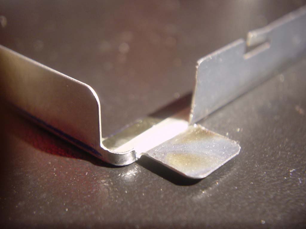
These long M3 screws will hold the display in place and the back fresnel lens too.
(CLICK TO ZOOM)
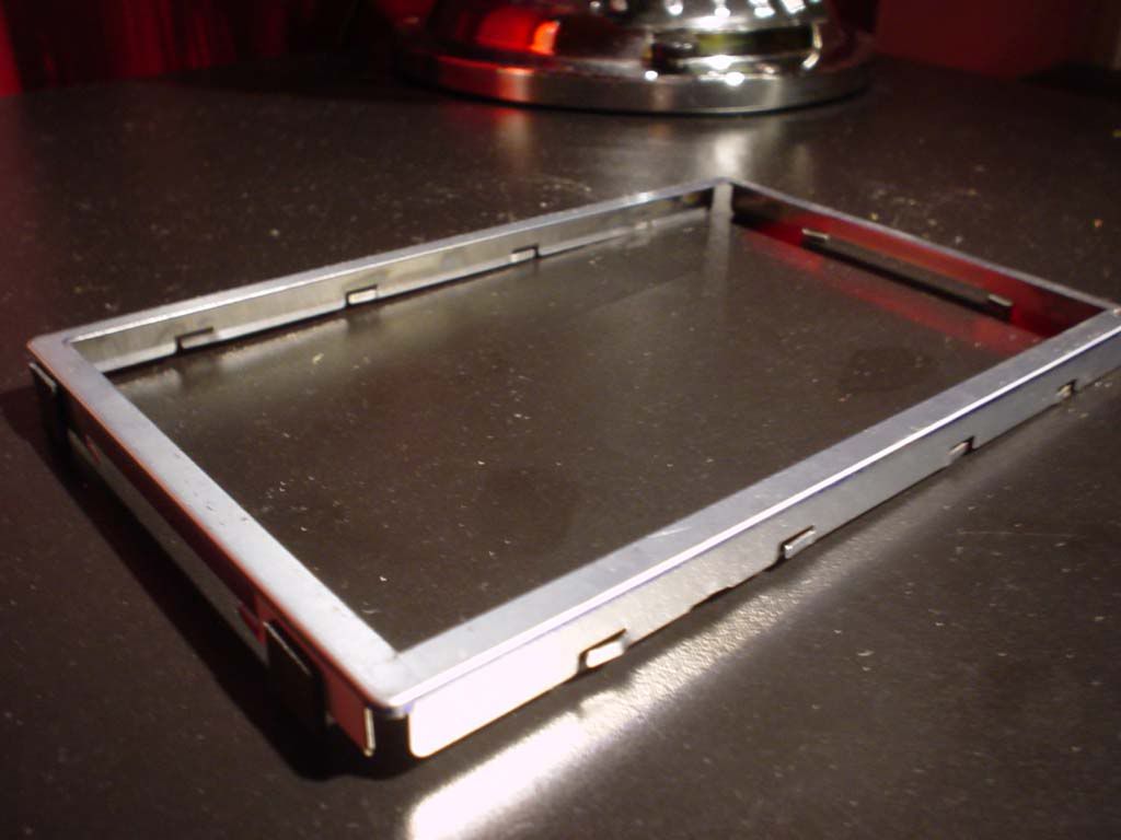
The TFT is positioned in the original metall frame and then the original black plastic frame (vissible in pic#8 in post #48) is attached on top and clamped down with a small piece of plexi, and underneath that plexi is a small piece of soft foam to prevent the display from being damaged.
(CLICK TO ZOOM)
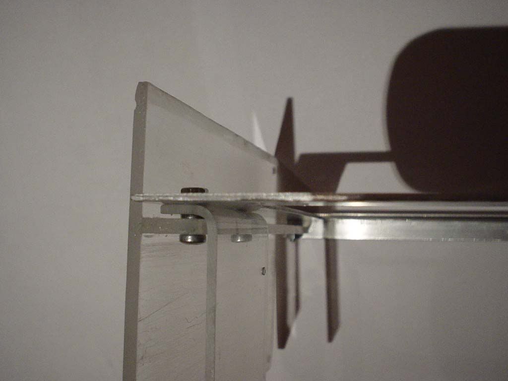
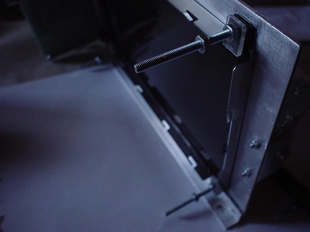
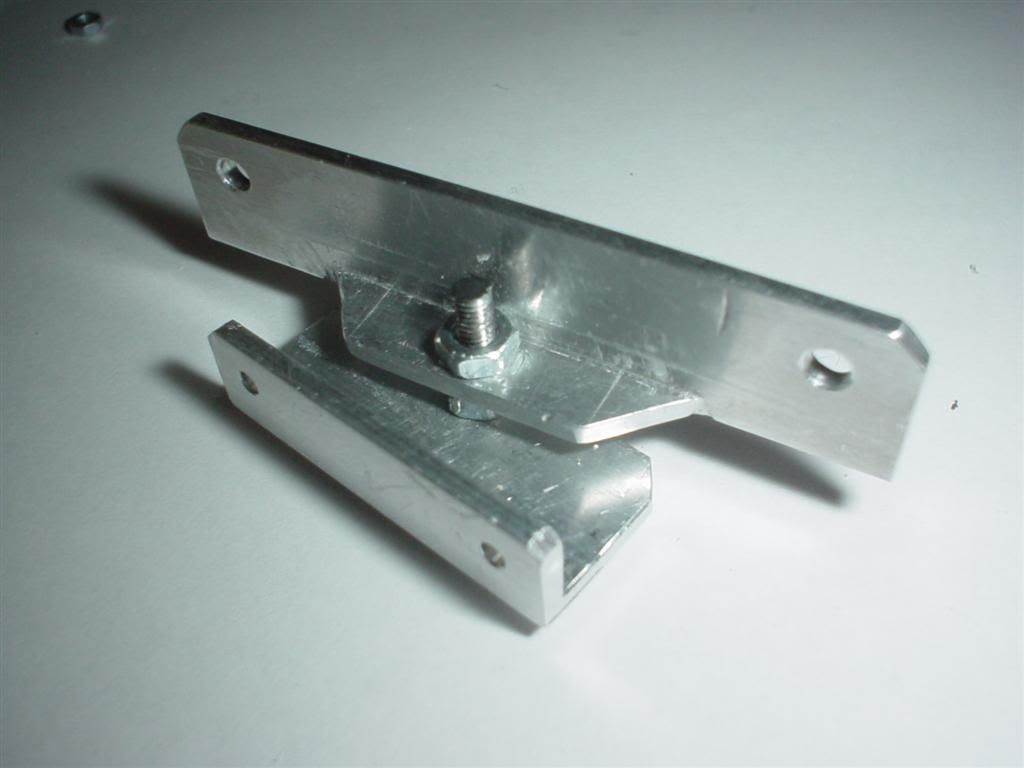
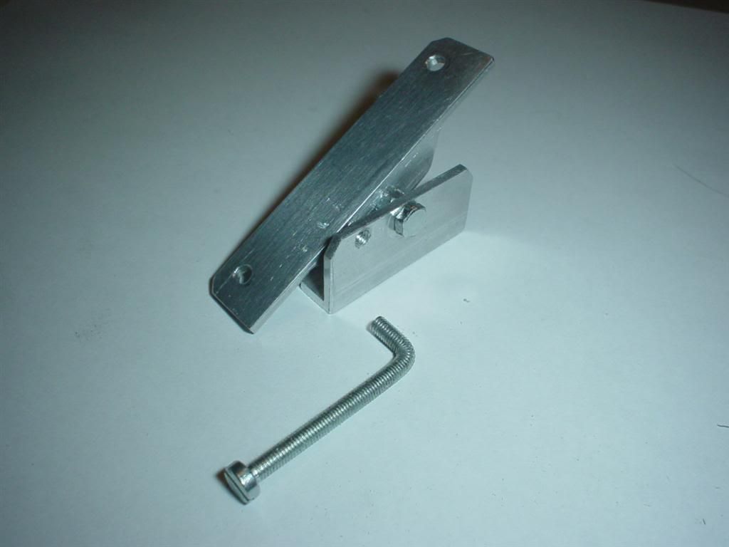
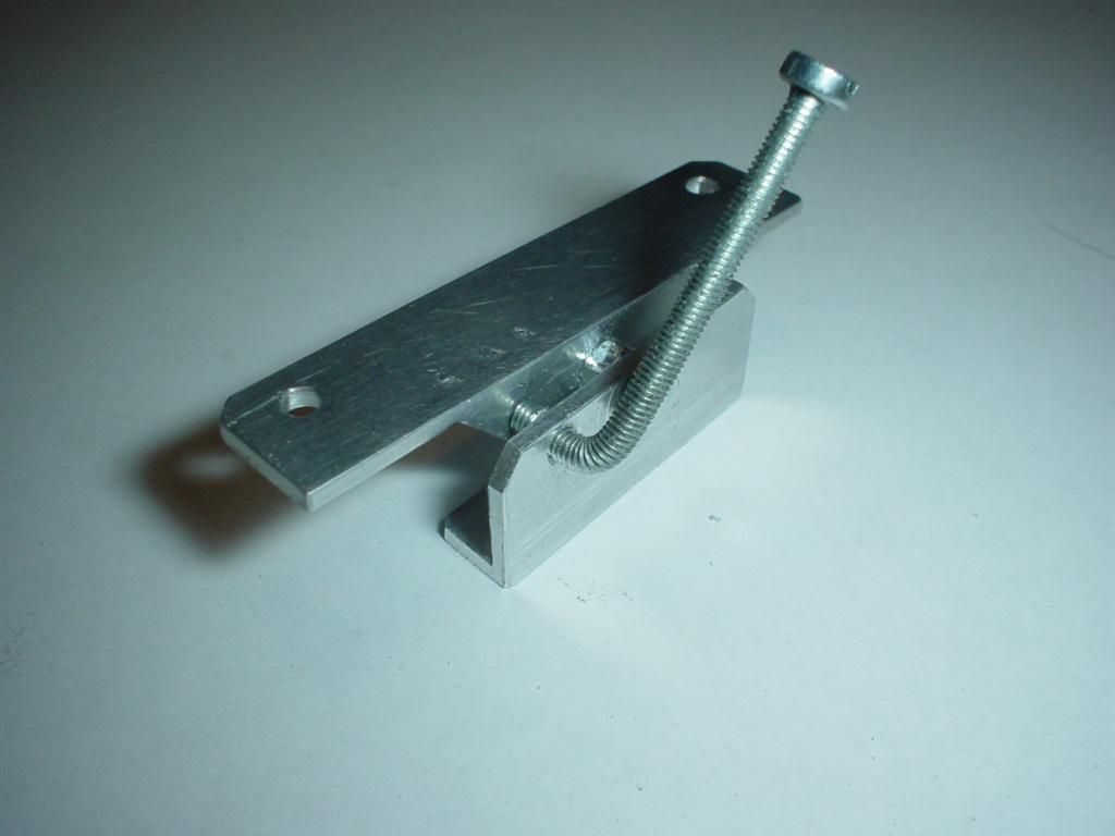
Here is my keystone mechanism. One on each side. These will hold the Front fresnel lens and allow me to tilt it.
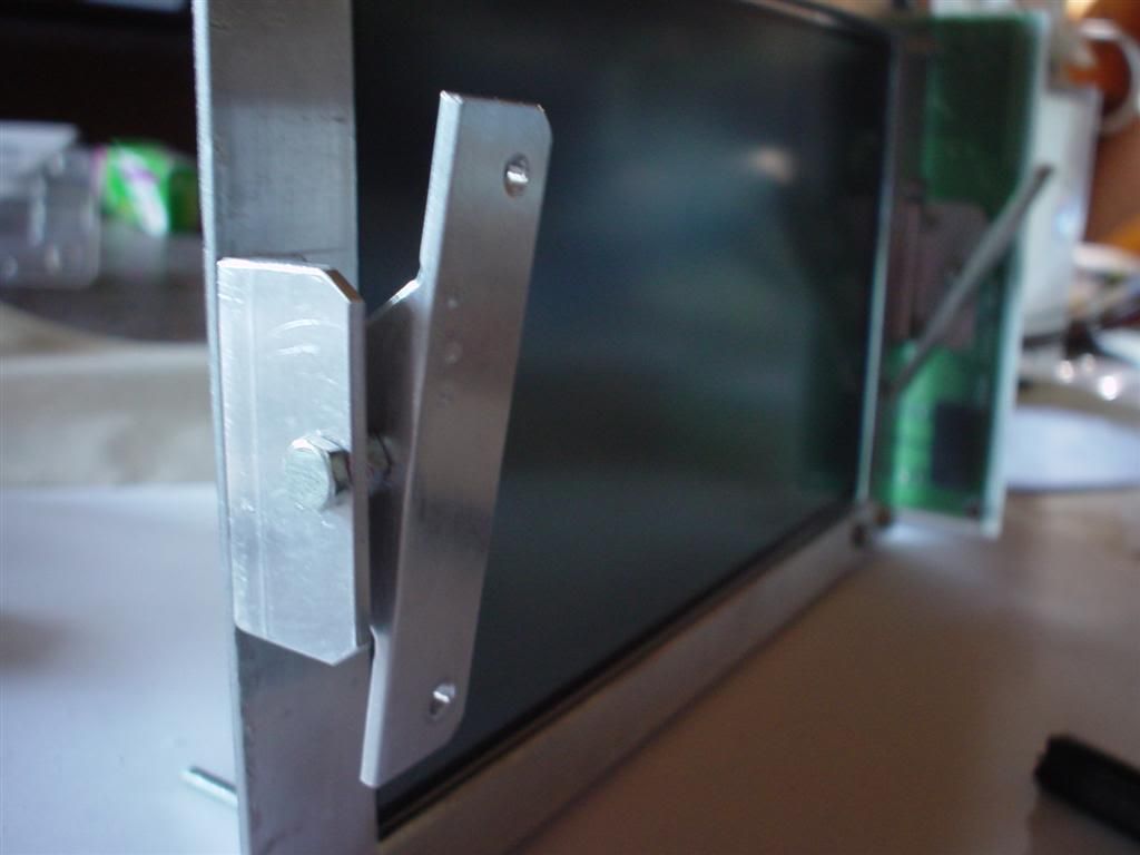
(CLICK TO ZOOM)
(CLICK TO ZOOM)
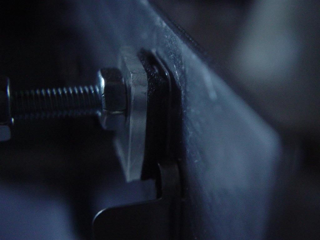
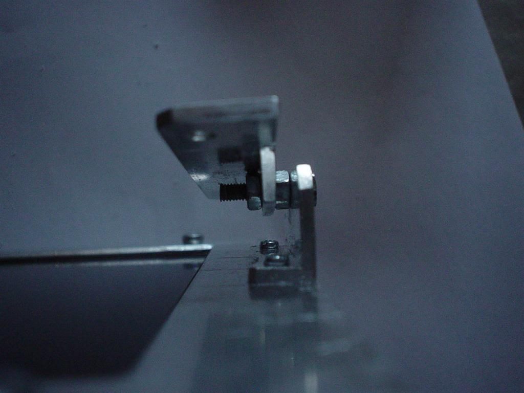
PAINT... :rock: .... The dark grey screw is a M3 screw that is not threaded all the way up to the the "hat". An M3 nut (light grey) is screwed on to the far edge of the threads and since there are no more threads it will stop. It leaves a small gap to the bottom L-bar that allows the dark grey screw to turn around freely. The top L-bar is secured tightly to the dark grey screw using a second M3 nut (light grey)

(CLICK TO ZOOM)
(CLICK TO ZOOM)
To be able to lock the lense in different positions I bent this M3 screw to a 90 degree angle and drilled a hole that I threaded to M3 size.
(CLICK TO ZOOM)
And..voila.. This works as a lever...turning it, it will press the top L-bar and it will stay in the desired position.
(CLICK TO ZOOM)
That's it for today.
/GNU
hehe ... ya i'm building 2 projectors my first though is a 15.4" 720p that i'm getting for 150$ and doesn't need a controller.... and later on when i get more money in a few months ill upgrade to a 1080p+controller 15.4 ..... as for myother monitor im gonna do a 12.1" 720p for my room (needs a controller)....
This way i have an upgrade path for my living room (15.4") on the cheapside... and the more expensive small 720p for my bedroom....
i wanted to do a 7" for my bedroom but feared the projection quality... and 12.1 seemed like a good size and since i found one with HD i figure wth...
can i talk to you on MSN sometime? cchance@gmail.com if you can i'd appreciate it
- Status
- This old topic is closed. If you want to reopen this topic, contact a moderator using the "Report Post" button.
- Home
- General Interest
- Everything Else
- The Moving Image
- DIY Projectors
- The_Gnu's Lilliput projector (lot of pics)