Hi
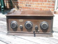
This is my first post in the tube forum, I have not had much experience with tubes although I do know the basics. I have an old radio that my grandfather used to use. He got it when he was about 9 years old and used it quite a bit. It is a Gerod, but I don't know were the model # would be located on it. I would like to get it to work once again, if possible. I think some of the tubes may have been replaced at sometime. There is one with a tested sticker with date...11/17/31. I believe the radio is older though. Anyway, here is a picture of it.
This is my first post in the tube forum, I have not had much experience with tubes although I do know the basics. I have an old radio that my grandfather used to use. He got it when he was about 9 years old and used it quite a bit. It is a Gerod, but I don't know were the model # would be located on it. I would like to get it to work once again, if possible. I think some of the tubes may have been replaced at sometime. There is one with a tested sticker with date...11/17/31. I believe the radio is older though. Anyway, here is a picture of it.
Attachments
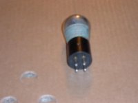
And this is one of the tubes, they all apear to be similar type, with 4 pins, but of course this doesn't mean they are of the same type, or are they.  I don't even know if any of them are good.
BTW, on the metel label inside with the patent and serial #'s there is a listing as "type M" if that means anything.
I don't even know if any of them are good.BTW, on the metel label inside with the patent and serial #'s there is a listing as "type M" if that means anything.
Attachments
rcavictim said:That's a beauty. Do a google for the Antique Wireless Association (AWA). They have many members, some probably willing to help you out.
WOW...fast reply.
AWA eh? Didn't think of them.
Thanx
I see a plate that says "Neutrodyne" - there's a Garod Neutrodyne listed here, but it only has four tubes... http://www.nostalgiaair.org/Resources/161/T0000161.htm
Vintage radio is what I did before I got into the whole Hi-fi thing. and there are a few words of wisdom I can pass on to one who is about to start restoring old radios.
1. Replace all old capacitors, espiecaly those awful wax paper capacitors
2. Unlike Hi-fi, in olds radios, most NOS or paper-in-oil caps are just a waste of money, you're going to notice no difference at all in the sound fidelity on an old radio
3. whatever you do, don't touch the chassis when it is plugged in, I made this mistake in my very first few days, and it was very nearly my last mistake. Those old, cheaper radios have everthing grounded to the chassis including the AC line, so when you plug it in, 120v of potential builds up between the chassis and the ground, all it needs is a path to the ground

Could you post the tube #s? I want to see if it's anything I am familar with
1. Replace all old capacitors, espiecaly those awful wax paper capacitors
2. Unlike Hi-fi, in olds radios, most NOS or paper-in-oil caps are just a waste of money, you're going to notice no difference at all in the sound fidelity on an old radio
3. whatever you do, don't touch the chassis when it is plugged in, I made this mistake in my very first few days, and it was very nearly my last mistake. Those old, cheaper radios have everthing grounded to the chassis including the AC line, so when you plug it in, 120v of potential builds up between the chassis and the ground, all it needs is a path to the ground
Could you post the tube #s? I want to see if it's anything I am familar with
I think this a battery radio, no line supply would have been used to power it.
Type M is this particular model of neutrodyne. The tubes might be good or not. I hazzard a guess there are probably a couple of 201/01 types in there. Common in old radios.
Antique electronic supply makes some power supply kits intended for powering vintage radios. see www.tubesandmore.com
I'm not familiar with this specific model, but most battery radios used either 1.5V or 5V filament tubes, B+ would be +45, +90V, +135V, any or all of these values might have been used. C- is the bias supply and typically ranged around -22.5V, but varied somewhat.
Unlike AC radios there usually aren't too many caps in these, they tend to be transformer coupled and use mica types in metal cans in the rf circuitry - in my experience these are usually still good. Paper caps are generally only found in the audio stages of these radios and as an occasional bypass cap.
Don't indiscriminately replace anything in this radio, and because of its age and relative rarity any parts that are replaced should be retained. Test it first, I have run across one or two battery sets that still worked ok without any repairs if they were well stored.
CBS240 said:Hi
This is my first post in the tube forum, I have not had much experience with tubes although I do know the basics.
It just occured to me that it makes sense then as you are doing, to start at the beginning!
Did you inherit the tabletop pedestal horn loudspeaker that this radio likely needs to be heard? I believe those were fairly high Z so don't expect to be able to put a modern 4-8 ohm loudspeaker on there and hear much of anything.
BTW I searched under vintage radios at ebay by chance out of curiosity about a weel ago and saw quite a few of the style radio you have, and their horns.
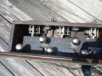
OK, I have removed the back so the bottom of the chassis can be seen. It appears there are large coils underneath. Are these those awful paper/wax caps or inductors? This is completely foreign to me as this radio is older than anyone on this forum I would say... ... since I have no documentation. It is obvious that it uses an external PS as there are wires from the back of the case labeled +B, -B, +A, +B DET, +B135, -C 4 1/2, A-C+, and B+AMP.
... since I have no documentation. It is obvious that it uses an external PS as there are wires from the back of the case labeled +B, -B, +A, +B DET, +B135, -C 4 1/2, A-C+, and B+AMP.Attachments
Re: Re: Vintage radio
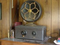
Like this one? This is a different radio my grandfather also had. I believe it is not as old, but there are more spider webs inside it than tubes! BTW, another future restoration project.
 I don't know if that horn is any good though. Would it be possible to use a transformer to match speaker impeadence to a modern speaker?
Edit: I found a tube number. One of them had it printed on the base.... Radiotron(RCA) UX-201-A. I believe some have been replaced at some time...in 1931 according to the labels on the tubes. There is another tube #, CX-301-A.
Edit2: the 301 tube is aperently the same as the 201.
Thanx
rcavictim said:
Did you inherit the tabletop pedestal horn loudspeaker that this radio likely needs to be heard? I believe those were fairly high Z so don't expect to be able to put a modern 4-8 ohm loudspeaker on there and hear much of anything.
BTW I searched under vintage radios at ebay by chance out of curiosity about a weel ago and saw quite a few of the style radio you have, and their horns.
Like this one? This is a different radio my grandfather also had. I believe it is not as old, but there are more spider webs inside it than tubes!
BTW, another future restoration project. I don't know if that horn is any good though. Would it be possible to use a transformer to match speaker impeadence to a modern speaker?Edit: I found a tube number. One of them had it printed on the base.... Radiotron(RCA) UX-201-A. I believe some have been replaced at some time...in 1931 according to the labels on the tubes. There is another tube #, CX-301-A.
Edit2: the 301 tube is aperently the same as the 201.
Thanx
Attachments
CBS240 said:OK, I have removed the back so the bottom of the chassis can be seen. It appears there are large coils underneath. Are these those awful paper/wax caps or inductors? This is completely foreign to me as this radio is older than anyone on this forum I would say...
Those huge coils are probably inductors, they really can't fail seeing as all they are is just a huge coil of wire. I am not personally familiar with Transmiting radios, I do mainly AM/FM, but those coils are used to help adjust the frequency the radio is picking up.
someone please feel free to shut me down on this hunch if I am wrong, but are those inductors that huge because the radio was made before the invention/industrialisation of Ferite core Inductors?
Some quick research finds that this tube base was first used in 1925.
http://www.radiomuseum.org/tubes/tube_ux201a.html
http://www.radiomuseum.org/tubes/tube_ux201a.html
Tom Bavis said:I see a plate that says "Neutrodyne" - there's a Garod Neutrodyne listed here, but it only has four tubes... http://www.nostalgiaair.org/Resources/161/T0000161.htm
There are two schematics in the pdf. One is called a model EM, and has five valves. I noticed Kevinkr suggested yours might be a model M.
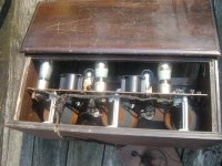
Yes I believe it is! It is labeled "type M" Which may stand for this type of circuit. The reciever part of this scematic looks quite similar to what I have observed inside. 3 coils, two transformers, 5 triodes. I haven't pulled the reverse engineer method yet though. Hmmm, could it be the correct scematic? Can't seem to find much documentation with any specs though. Suppose I may have to pull it apart and look.
Also, does anyone have a good method for testing these type of tubes? I have a buch of small power transformers I can put the secondaries in series to obtain just about any isolated voltage. They may or may not be any good. It appears a couple of tubes have been replaced, there are some made under Cunningham's name and others are labeled from Radiotron, all from RCA.
Suppose I may have to pull it apart and look. Also, does anyone have a good method for testing these type of tubes? I have a buch of small power transformers I can put the secondaries in series to obtain just about any isolated voltage. They may or may not be any good. It appears a couple of tubes have been replaced, there are some made under Cunningham's name and others are labeled from Radiotron, all from RCA.
Attachments
Most Hickok tube testers will test the 01/201/301.
These have a 5V filament at 250mA, and are direct heated.
This radio dates from sometime in the second half of the 1920's. AC powered sets started to appear around 1927. (I have an ac powered radiola 18 made that year)
Chances are if this radio was not used for too many more years those tubes are still good. I have pulled high hour 01s on several occasions and they have been weak to good, never totally bad except if open filament. Keep your fingers crossed, the 01/201/301 are far less common than the 26, and fairly expensive when you can find them new.
Aircoils were used because low loss ferrites for rf were still a few years down the road when this radio was made.
I saw some mica caps in the photo, these are probably still good. I have a bunch of used ones I got for a shortwave breadboard radio I am building - they were just fine. (Using Cunningham 301)
I suspect this radio might be in (near) running condition, I'd deal with the psu issue first, see if it runs, and them repair as necessary.
Sometimes the audio interstage transformers in old sets go open, this is particularly the case if the set was ever stored in a damp location. AES sells a replacement bobbin that in many cases is adaptable to the original core for about $12 last time I checked.
AES probably has a power supply kit that can be adapted to power this radio. You may also be able to find people selling these on eBay.
Modern speakers even with transformers don't have the requisite sensitivity. Most of these radios are hard pressed to produce 100mWrms at maximum power and would sound pretty bad doing it.The old horns had massive amounts of acoustical gain, resulting in typical sensitivities equivalent I roughly estimate at up to 110dBspl or more at 1W.
EICO Model 666 will test your old tubes, and probably the Model 625 will too. Or for sure the Model 667 with 615 socket adaptor.
Some of that style tube had the number (type) on the side of the base, some on the top of the glass. To read faded numbers try first chilling the tube in fridge or freezer. When brought back to room temperature the tube sweats and the number may magically become visible for a short time.
Some of that style tube had the number (type) on the side of the base, some on the top of the glass. To read faded numbers try first chilling the tube in fridge or freezer. When brought back to room temperature the tube sweats and the number may magically become visible for a short time.
- Status
- This old topic is closed. If you want to reopen this topic, contact a moderator using the "Report Post" button.
- Home
- Amplifiers
- Tubes / Valves
- Vintage radio