I NEED HELP WITH THE AMP THE FEEDBACK AND AUDIO LEVAL OUT WHEN USING A MUSICAL INSTRMENT ?
I HAVE TRY LM380N BUT REALY THE SAME RESULT
NOT REALY SURE WHAT AMP THIS IS CALLED?
THE PARTS IAM USING ARE MJE15034 MJE15035 TIP35C TIP36C
FOR THE POWER SECTION
WHAT WOULD ADD AND PARTS CHANGE TO THE SCHEMATIC ?
http://cache.national/ds/lm/lm386.pdf
http://onsemi.com/pub/collateral/mje15034-d.pdf
http://onsemi.com/pub/collateral/tip35a-d.pdf
Attachments
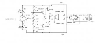
No, it will not work this way, not with LM386 - even the datasheet should show it! First of all, LM386 is a single supply chip with a maximum Vcc of around 12 V. Even though you'd drop the +-60 to +-6 V at the chip Vcc/gnd and the chip would work with dual supply (i highly doubt it) it would still have an output voltage swing limited to around +- 5 V, perhaps even less. Even an ordinary opamp with +-15V output would not be able to drive the +-60 V supply even near it's limits. You should ditch the LM386 and amplify the opamp Vcc/Vee pin currents to gain a higher voltage swing, then use that to drive the output transistors. There's other huge problems too, the circuit here would undoubtedly burst into flames. Spare your components and do not build this circuit! Instead i'd recommend you to study power amplifier circuit theory. You have a lot to learn.
Teemu K
Teemu K
") also, he should tie the chip amp's output pin to the middle of the diode chain, or else he will have a DC offset at the output.
also, he should tie the chip amp's output pin to the middle of the diode chain, or else he will have a DC offset at the output.It might be that he's mistaken with the two chips but the pinout of LM386 seems to be correct in the schematic. Anyway, even for LM3886 the +-60V is still way too high. The voltage dividers at the supply of gain chip would benefit from capacitors, 0.1 ohm emitter resistors are IMO too low value, the filter caps are missing the ground connection and the diode chain should be connected the other way around. Probably the series diodes wouldn't be a reliable enough solution anyways. And whats the idea of having an inbalance at the output? (1k in parallel with 2.2k vs. 2.2k in parallel with 47k). The design clearly isn't up to the power levels it tries to achieve. With some "minor" corrections, lower supply voltages and an opamp instead of LM386 (plus proper feedback loop of course) it might even work.
- Status
- This old topic is closed. If you want to reopen this topic, contact a moderator using the "Report Post" button.