Hi all. I was half way through measuring triode data for a pentode when it occured to me there are two possible methods. The question relates more to standard practices, which manufacturer data sheets don't make clear. Do published plate curves for triode-connected pentodes include the screen current? Since screen current passes through the OPT and contributes to the output my measurements will include it but what am I seeing on data sheets? Thx in advance.
I think the point was that when the screen is connected to the plate, it is the plate, electrically. IMO it makes no sense to measure the current of a triode connected pentode at a point between the plate and where the plate meets the screen, and to only measure that branch. I have seen ambiguities before, and this one seems more obvious to me than some.
Plate current on triode conencted graphs DEFINITELY mean pentode plate + pentode screen total current, as the two conencted together represent a triode plate.
It would, however, be nteresting to know how the currents are actually distributed between pentode plate and screen in some applications, in particular where it may be suspected that screen dissipation is a limiting factor, or when attempting to run a tube outside published specs(*).
(*) When triode curves are not published, the safe approach is to limit plate voltage at the maximum published spec screen voltage for the pentode. This, however, may not be a true maximum rating in triode mode as there are other factors to consider - case in point being tbelab's experiments.
Hi ilimzn. You illustrate the ambiguity perfectly because the graphs are definitely not labelled 'plate + screen current' and designers as a rule don't tie them directly together. A resistor separates them at a minimum. I'll admit to likely overthinking where a simple answer exists and did my curves using the combined screen/plate currents separated by the planned 1000 ohm resistor.
You bring up another great point I wanted to ask. My understanding is the maximum screen voltage is specified to prevent flashover to the grid. Is that correct? If so it appears to provide a guidline for using a tube in circuits in which not all parameters are stressed. Transmitter tubes are a great example. Let's say the max allowable grid swing is specified at +-100, screen voltage as 400, plate voltage at 1200. This implies a peak permissible grid-screen voltage of 400 (screen V) - 100 (grid bias) -100 (grid max neg swing)=600. If used for a low power audio amp requiring +-20 volts grid swing, does this raise the permissible screen voltage to 600-20-20=540 volts? This analysis also ignores that transmitter tubes are spec'd at tens of megahertz. Audio's greatly reduced bandwidth further implies less hammering of the screen-grid capacitance, though it might not be a significant consideration. Wishful thinking?
You bring up another great point I wanted to ask. My understanding is the maximum screen voltage is specified to prevent flashover to the grid. Is that correct? If so it appears to provide a guidline for using a tube in circuits in which not all parameters are stressed. Transmitter tubes are a great example. Let's say the max allowable grid swing is specified at +-100, screen voltage as 400, plate voltage at 1200. This implies a peak permissible grid-screen voltage of 400 (screen V) - 100 (grid bias) -100 (grid max neg swing)=600. If used for a low power audio amp requiring +-20 volts grid swing, does this raise the permissible screen voltage to 600-20-20=540 volts? This analysis also ignores that transmitter tubes are spec'd at tens of megahertz. Audio's greatly reduced bandwidth further implies less hammering of the screen-grid capacitance, though it might not be a significant consideration. Wishful thinking?
I have never thought about this!
Most tube data sheets state that screen is tied to plate. I have not noticed that a resistance is inserted in the screen line - not for my data sheets for KT66, KT88, 6L6 or EL34. In practical circuits it is usually about 100 ohm, and I am not sure that this is not often just a pious gesture. I grew up with tubes but cannot recall that anybody ever mentioned parasitics as a result of not putting a resistor in. But for the cost of a resistor.....
Inserting appreciable resistance would bring G2 transfer linearity into the picture, and with that resistor tied to plate the matter is not simple. I have never seen Vg2/Ig2 characteristics vs. G1 voltage. It is known that for UL operation of EL34s distortion is lower with a G2 serie resistor of 1K, but that is the only tube where the data sheet specifies it. Many UL circuits for 6L6, KT66, KT88 use no screen resistor.
Screen dissipation is part of the limiting factor. In pentodes, where maximum screen current occurs when the plate is at the lowest part of its swing, it is of greater importance than in triode connection where the screen goes down with the plate.
Also, tube data sheets are interesting. Maximum voltages for the 6L6GC is 500V plate and 450V screen, but the latter is 500V under UL conditions. For the 7027 it is 600V and 500V respectively, but with G2 spec. raised to 600V under UL conditions. For the EL34 the max. plate voltage is 800V and screen 425V, but at zero plate current the ratings rise to 2KV and 800V respectively. (This seems to be an indication of maximum swing.)
I once discussed this with a friend who previously worked at the Philips Tube Manufacturing Plant at Eindhoven, Holland, where he tested tubes. He said that data sheet maximum voltages are very conservative, for worst conditions. They may be safely exceeded depending on the application and operating conditions. But by how much.......? With some uncertainty involved in the quality of present-day tubes, such a decision is not easy.
Regards.
Hi folks,
I have traced quite some pentodes as triodes, look here.
Also, I have studied and compared factory sheets with own measurmensts. So maybe I can contribute a bit from practice.
1. The plate current shown in manufacturers sheets for triode(d) op actually always is the sum of Ia + Ig2, measured at the junction of plate and g2 feeds, regardless of a 100 ohms resistor present between g2 and that junction, or not.
2. As for precision, a 100 Ohms resistor used between g2 and plate realy doesn´t make a difference at all. The voltage drop of at most few volts at g2 is absolutely neglegible, you will see no difference at all between a trace made w/ or w/o a 100 Ohms resistor between g2 and plate.
3. In measuring (and amp building) practice, I strongly suggest to always use the 100 Ohms resistor indeed, tied as close as possible to g2 pin. Also, always use a g1 stopper when tracing curves. If you don´t, be aware that especially with medium and high gm tubes you almost inevitably will get parasitic oscillations - you may not even notice them except maybe for "strange" or changing current readings, because they might occur so deep into the RF band (two-to-three digit MHz figues) that even your cool 50Mhz scope might not resolve them! You have been warned.
4. If accessible at a separate pin, always tie g3 to cathode directly. Tying g3 to plate can give considerably different curves (usually higher mu and higher gm, linearity usually gets considerably worse).
4a. If the tube you are tracing has internal shielding accessible at a separate pin, use it tied to cathode, too.
5. Give tubes, especially NIB ones, *plenty* of time to stabilize and settle before tracing, and then some more. Previously unused indirectly heated cathodes need time to develop their active cathode surface, indeed. This is simply due to the way cathodes are manufactured. They won´t stabilize when only being heated, so you have to apply reasonable plate current + voltage to stabilize new tubes, too. Usually, I run them at about 50%-75% max Pd during stabilizing, to give a figure. Don´t underestimate this hint! While some small signal pentodes might take only 1/2 an hour to reach stable long term conditions (that is what you want to trace!), bigger types might take much longer. I had some NOS 807 that took almost 2 days of simmering until they stopped to drift! They probably had old style inter-layer constructed cathodes.
5. Always, I said always, measure several samples, or you won´t know if you are just tracing a "typical" one or an "untypical" (or bad) one. You don´t need to make complete traces to be sure, just pick a few (say, 3 or something) intelligently chosen op points and compare those among all your samples. If in doubt, use the tube for tracing that comes closest to the average results of the "healthy" ones out of your samples.
Tom
Tubes4e4 said:4. If accessible at a separate pin, always tie g3 to cathode directly. Tying g3 to plate can give considerably different curves (usually higher mu and higher gm, linearity usually gets considerably worse).
Thanks Tom! Many of your tube curves are part of my .pdf library. Have you traced one with G3 pulled negative to cathode? I see this commonly used in posted builds but never an explanation for its effects or benefit.
Hi SY,
A few real good PSUs (essential - I even built a tubed one exactly for this purpose, it is on my homepage, too), a few good DVMs (mostly for convenience)and a few resitors, and MS Excel to visualize the data. The exact setup depending on what to measure.
Tracing pentode UL op curves certainly requires the most "complicated" setup, but still is very easy to do when you invest a second or two in thinking about how the screen voltage depends on plate voltage and UL-ratio: For the screen feed, a simple two-resistor voltage devider (giving the ratio) and a floating PSU (giving the base-offset voltage) will do.
Tom
SY said:Tom, what test setup did you use to generate the curves? [/B]
A few real good PSUs (essential - I even built a tubed one exactly for this purpose, it is on my homepage, too), a few good DVMs (mostly for convenience)and a few resitors, and MS Excel to visualize the data. The exact setup depending on what to measure.
Tracing pentode UL op curves certainly requires the most "complicated" setup, but still is very easy to do when you invest a second or two in thinking about how the screen voltage depends on plate voltage and UL-ratio: For the screen feed, a simple two-resistor voltage devider (giving the ratio) and a floating PSU (giving the base-offset voltage) will do.
Tom
Hi rdf,
Not yet, but certainly I can do that with the next pentode I measure with has the surpressor available at a pin.
On the theory, there should be something in the Barkhausen books; I´ll have a look.
Tom
Have you traced one with G3 pulled negative to cathode? I see this commonly used in posted builds but never an explanation for its effects or benefit.
Not yet, but certainly I can do that with the next pentode I measure with has the surpressor available at a pin.
On the theory, there should be something in the Barkhausen books; I´ll have a look.
Tom
Hi rdf,
Well, I did, but sorry, I cannot give you a translated "short" summary; my English simply is to weak to translate German lecture textbook extracts to English.
Essentially, the function of the surpressor grid as such doesn´t depend on the actual exact voltage unless it is not negative to the cathode but on the space charge vector situation at its place in the actual pentode.
In ultra-short, the Barkhausen text says g3 must be negative to g2, but not negative to cathode (and I trust him). The most simple method of ensuring this is to connect g3 to cathode, of course, as done often internally in pentodes to spare a pin or pin connection.
Different voltage values for g3 between Vcathode and Vg2 will lead to different efficiency as surpressor, of course.
Also, one can use g3 as an additional steering grid (that´s nothing new and actually being put to practical use in RF mixer stages).
Nevertheless, g3 negative to cathode will do harm to the surpressor fucntion per se.
This should show in tracings, of course; I would expect some sort of non-smooth curves at plate voltages < g2, as with the well known tetrode "kink", but certainly not as prominent (depending on how much the surpressor function is harmed).
Hope it helps,
Tom
On the theory, there should be something in the Barkhausen books; I´ll have a look.
Well, I did, but sorry, I cannot give you a translated "short" summary; my English simply is to weak to translate German lecture textbook extracts to English.
Essentially, the function of the surpressor grid as such doesn´t depend on the actual exact voltage unless it is not negative to the cathode but on the space charge vector situation at its place in the actual pentode.
In ultra-short, the Barkhausen text says g3 must be negative to g2, but not negative to cathode (and I trust him). The most simple method of ensuring this is to connect g3 to cathode, of course, as done often internally in pentodes to spare a pin or pin connection.
Different voltage values for g3 between Vcathode and Vg2 will lead to different efficiency as surpressor, of course.
Also, one can use g3 as an additional steering grid (that´s nothing new and actually being put to practical use in RF mixer stages).
Nevertheless, g3 negative to cathode will do harm to the surpressor fucntion per se.
This should show in tracings, of course; I would expect some sort of non-smooth curves at plate voltages < g2, as with the well known tetrode "kink", but certainly not as prominent (depending on how much the surpressor function is harmed).
Hope it helps,
Tom
Double thanks Tom, particularly for the translated synopsis. The issue of G3, no surprise, has come up before on this forum. Tubelab traced plate curves (power pentode I can't recall at the moment) and found the two connections had vastly different results. I compared the THD of a CCS-loaded, gridleak biased E180F for both and found no difference above experimental error. So it was interesting to read another first-hand account. It's common to read of builders biasing G3 below the cathode, now I'm wondering if they linearize the tube across a small operating range at the expense of the rest, or just prefer the audible deviation.
I'm finishing up a two-stage RC-coupled test amp using an 800-series DH pentode as a final. It would be a trivial change to place a 10K pot from the cathode bias resistor to ground and examine the distortion spectra of different G3 voltages below cathode. I'll post some results when I get around to it.
I'm finishing up a two-stage RC-coupled test amp using an 800-series DH pentode as a final. It would be a trivial change to place a 10K pot from the cathode bias resistor to ground and examine the distortion spectra of different G3 voltages below cathode. I'll post some results when I get around to it.
Tubelab traced plate curves (power pentode I can't recall at the moment) and found the two connections had vastly different results.
It was an EL-34, an old one at that, but it was all I had at the time. There was a thread that asked about tying G3 to the plate, so I tried it.
http://www.diyaudio.com/forums/showthread.php?s=&threadid=67422&highlight=
The results showed a marked kink in the curves when G3 is tied to the plate, although not everyone believed the results.
It was common in the horizontal output stage of old TV sets to tie G3 to a negative voltage source. This was done to prevent "Barkhausen oscillation". Many sweep tubes have a spec showing the maximum negative G3 voltage. Every one that I have seen is -30 volts.
My experiments have shown that some sweep tubes (6AV5, 6LW6) can be operated far in excess of the screen ratings in triode mode, while others (6CD6) show signs of glowing grid syndrome at slightly above the maximum ratings. I would suspect that this has more to do with each tubes internal construction than a general rule.
Hi tubelab,
Oh, I do. At least the leftmost two curves look like showing hints of secondary emission "kinks" , not quite as much as a plain tetrode, but certainly visible.
Hmmm .... typical deflection circuits run the plate voltage way below the screen. Assuming a non- working or hampered surpressor function, they would operate in the non-stable area conditions of negative plate impedance (the "hill-valley-hill" kink part of a plain tetrode curve), which certainly is prone to Barkhausen oscillations. The pentode g3 function prevents this by eleminating the secondary emission, so the plate can source some serious current w/o danger of running into negative impedance (and hence oscillations).
So, pentodes with g3 present and working (or beam power tetrodes, giving a similar result) obviously are better suited to that TV deflection duty/task than (plain) tetrodes. So far, so good.
What is irritating: That Barkhausen suggests g3 will cease function as supressor when being operated below cathode, and real world TV deflection circuitry does exactly this to prevent Barkhausen oscillation, which is a contradiction.
I dunno how to resolve this at the moment, but maybe the fact that almost all "deflection duty tubes" have real serious cathode area and massive peak current capabilities (say, the 2 amps EL/PL509 can do) and probably operate in or near space charge saturation conditions may give internal working conditions that are vastly different from "ususal" pentode operation (no space charge saturation, Vg2 considerably lower than Vplate) that require g3 to be more negative than cathode in this case.
Tom
The results showed a marked kink in the curves when G3 is tied to the plate, although not everyone believed the results.
Oh, I do. At least the leftmost two curves look like showing hints of secondary emission "kinks" , not quite as much as a plain tetrode, but certainly visible.
It was common in the horizontal output stage of old TV sets to tie G3 to a negative voltage source. This was done to prevent "Barkhausen oscillation".
Hmmm .... typical deflection circuits run the plate voltage way below the screen. Assuming a non- working or hampered surpressor function, they would operate in the non-stable area conditions of negative plate impedance (the "hill-valley-hill" kink part of a plain tetrode curve), which certainly is prone to Barkhausen oscillations. The pentode g3 function prevents this by eleminating the secondary emission, so the plate can source some serious current w/o danger of running into negative impedance (and hence oscillations).
So, pentodes with g3 present and working (or beam power tetrodes, giving a similar result) obviously are better suited to that TV deflection duty/task than (plain) tetrodes. So far, so good.
What is irritating: That Barkhausen suggests g3 will cease function as supressor when being operated below cathode, and real world TV deflection circuitry does exactly this to prevent Barkhausen oscillation, which is a contradiction.
I dunno how to resolve this at the moment, but maybe the fact that almost all "deflection duty tubes" have real serious cathode area and massive peak current capabilities (say, the 2 amps EL/PL509 can do) and probably operate in or near space charge saturation conditions may give internal working conditions that are vastly different from "ususal" pentode operation (no space charge saturation, Vg2 considerably lower than Vplate) that require g3 to be more negative than cathode in this case.
Tom
It was common in the horizontal output stage of old TV sets to tie G3 to a negative voltage source. This was done to prevent "Barkhausen oscillation". Many sweep tubes have a spec showing the maximum negative G3 voltage. Every one that I have seen is -30 volts.
My memory must be getting fuzzy with age. I was looking through some old electronics books looking for sweep tubes that I have forgotten about, and I realize that G3 was tied to a POSITIVE voltage source of 10 to 30 volts to eliminate Barkhausen oscillation. Sorry for the confusion that I may have created. It has been about 35 years since I worked on TV's.
")
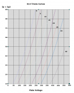
And after all that it turns out the tube wasn't suited to my iron, though it was exciting experimenting with the manufacturer's safety factor on a 500 volt rated OPT. However the measured curves look very interesting so I'll post them with the warning they represent a single sample, albeit a new sample. They're also as far as I know the only 814 triode-mode curves to be found.
Attachments
- Status
- This old topic is closed. If you want to reopen this topic, contact a moderator using the "Report Post" button.
- Home
- Amplifiers
- Tubes / Valves
- Measuring Triode-Connected Pentode Curves