Balanced line receivers' schematics are easily found. I didnt' find much however with regards to trimming offset due to mismatch in the common-mode voltage.
My application is at the output of a pcm1798 DAC. It has differential, current-out outputs which need to be turned to unbalanced. Digital silence is at -3.5ma, which means offset after the I/V opamps. Most of it will be cancelled but a few mv of offset could still be there. I would like to avoid a coupling cap at the output of the DAC so what's the best way of getting rid of the possible offset left ?
The INA134 has an offset adjustment circuit but with a range limited to 300µV. And it is directly referenced to the power rails, something I'd prefer to avoid.
If anyone can point me to something, it'd be much appreciated.")
My application is at the output of a pcm1798 DAC. It has differential, current-out outputs which need to be turned to unbalanced. Digital silence is at -3.5ma, which means offset after the I/V opamps. Most of it will be cancelled but a few mv of offset could still be there. I would like to avoid a coupling cap at the output of the DAC so what's the best way of getting rid of the possible offset left ?
The INA134 has an offset adjustment circuit but with a range limited to 300µV. And it is directly referenced to the power rails, something I'd prefer to avoid.
If anyone can point me to something, it'd be much appreciated.
00940 said:...... It has differential, current-out outputs which need to be turned to unbalanced. Digital silence is at -3.5ma, which means offset after the I/V opamps. Most of it will be cancelled but a few mv of offset could still be there. I would like to avoid a coupling cap at the output of the DAC so what's the best way of getting rid of the possible offset left ?
....
Hi,
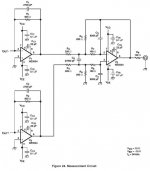
The offset at the output of the I-V converter opamp is defined by the Iout and resistor Rf. If you are using standard resistors with 1% tolerance, the offset between the positive and negative outputs can be arround 40mV for Rf=820 ohm +/-1% at worst. This offset appears at the output of the diff. opamp (gain=1). So, IMO, the best and simplest solution is to trim the Rf resistors in the I_V converters to obtain zero DC at the diff. opamp's output.
Regrads,
Milan
Attachments
I will use resistors hand matched to more like 0.1%. Still, this can give me something like 4mV, which is still too much for my taste (feeding it to a headphone amp with a gain of 11 would give me 44mv at the output, which is too much). And then on top of this, there is the offset of the opamps themselves (typically 1 or 2ma).
Trimming the I/V resistors means to put a trimmer in the I/V position and it's something I'd like to avoid since I plan to use high quality resistors in this particular position.
If I wanted to put a servo integrating the offset at the output, where should I feed it back ?
Trimming the I/V resistors means to put a trimmer in the I/V position and it's something I'd like to avoid since I plan to use high quality resistors in this particular position.
If I wanted to put a servo integrating the offset at the output, where should I feed it back ?
- Status
- This old topic is closed. If you want to reopen this topic, contact a moderator using the "Report Post" button.