Greetings.
I would like advice on the effectiveness of a common emitter/common source output stage (emiters/sources connected to the supply). I wonder why it is seldom used. I can think of two advantages: there would be small voltage swing (~4V for MOSFETS, ~0.2V for bipolar) and less miller effect for the driving stage. Also the output stage would give voltage gain as well as current gain. Are there disadvantages?
Opinions appreciated.
Acoustic Absorb said:less miller effect for the driving stage
Colud you explain how?
Try ‘common emitter output’ in exact phrase search for a few threads,
Cherry has good series of JAES papers on output impedance in audio amplifiers, also some Radio Electronics/Wireless World articles
I’m sure you can find “no feedback” advocates anxious to rehash the emitter followers are not unity gain feedback argument too
Cherry has good series of JAES papers on output impedance in audio amplifiers, also some Radio Electronics/Wireless World articles
I’m sure you can find “no feedback” advocates anxious to rehash the emitter followers are not unity gain feedback argument too
")
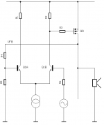
Miller effect would be reduced because the stage (Q1B in my schematic) driving the output tansistor will have just the VGS of the output transistor on its output whereas it would have the whole output signal if an emitter follower/source follower output stage is used. Therefore the miller capacitance in Q1B will be carying just ~4V instead of ~20 V for a source follower output.
Re output impedance I need to read up on this subject. Am I wrong in thinking that a high open loop gain will give a low output impedance?
I am attempting to include a shematic in this post.
Re output impedance I need to read up on this subject. Am I wrong in thinking that a high open loop gain will give a low output impedance?
I am attempting to include a shematic in this post.
Attachments
The main problem with common emitter output is that the output impedance is high and therefore the open loop transfer function ('forward path') is highly dependent on load impedance.
I guess you know that amplifiers are tested (THD) mainy on resistors and real life dynamic speakers are most awfull loads onecould imagine: non-linear, highly reactive especially at resonance and HF and with crappy crossovers, highly thermally modulated, really microphonic (not like capacitor yada yada bla.., in fact they are microphones), even slightly hysteretic.
Keeping amp's forward path very linear, low phase shifting and so on.. becomes of little sense.
The only sensible way to use common emitter output is in my view apply very local feedback around output devices (Sziklai, CFP output) together with global feedback.
regards
Adam
Acoustic Absorb said:Miller effect would be reduced because the stage (Q1B in my schematic) driving the output tansistor will have just the VGS of the output transistor on its output whereas it would have the whole output signal if an emitter follower/source follower output stage is used. Therefore the miller capacitance in Q1B will be carying just ~4V instead of ~20 V for a source follower output.
Well, yes, if you are talking about local miller effect for the stage. However, what about the miller effect for Q9? Remember that this can have a Cgd one or two orders of magnitude higher than your driving BJT and, it is multiplied by the effective gain of Q9. Also, Cgs of Q9 is usually 3-5 times higher than it's Cgd - and the driver stage now has to drive the full Cgs now in addition to the 'millerized' Cgd. Oh, and let us not forget: Both Cgs and Cgd are nonlinear, with Cgd usually being smaller but more nonlinear for small Vds, except now this is increased by Q9 miller effect.
Therefore, you have decreased driver stage miller effect by a factor of about 5, whereas you may have increased the potentially more nonlinear load capacitance by an approximately same, or even higher factor.
Look at a source follower stage - the contribution of the larger of the two capacitances (Cgs) is REDUCED considerably by the gm of Q9 in a follower application, wuite usefull as it is about 3-5 times higher than Cgd to begin with. In other words, you get the minimum effective capacitance to drive in a source follower config, and it is a rather large difference (for something like an IRFP240 it's a factor of about 5).
This may pose a much larger problem than driving the miller capacitance of your driver by the previous stage - the latter can be solved by several means, one of the more obvious being a cascode. I am not saying common source is a bad thing, just that you have to be careful when making sweeping statements - you might have just traded one miller effect for another, possibly worse one.
In thread "Blowtorch" , JustCallMeDad, wrote
----However it is true that “drain or collector” outputs appear to give bests listening results as it seems that the action of the load (cable, following input stage) influence more the behaviour of the device configured in follower mode (source/emitter output), by a better circuit isolation to the external world (especially true with fet/mosfets). ----
which may be worth of consideration in the present discussion.
Source follower has an output impedance given by roughly 26/mA of current, where the output impedance of the collector is reduced only by local or global feedback, which of course is considerable.
However, as in any feedback situation, care needs to be taken with phase shift to avoid instability, and the CFP (or Sziklai pair) is notorious for ringing operation at the switching transition, so is rather tetchy in Class AB.
Cheers,
Hugh
However, as in any feedback situation, care needs to be taken with phase shift to avoid instability, and the CFP (or Sziklai pair) is notorious for ringing operation at the switching transition, so is rather tetchy in Class AB.
Cheers,
Hugh
A common emitter output amplifier :
Class AB design
Wim de Jager, van Tuy & van der Ven
Electronics World December 1999, p982
This Class AB audio power
amplifier features excellent
stability without needing
stabilising networks. Its new
driver stage eliminates crossover
distortion and it has a saturation
preventing scheme for fast
recovery from clipping.
- Status
- This old topic is closed. If you want to reopen this topic, contact a moderator using the "Report Post" button.
- Home
- Amplifiers
- Solid State
- Common Emiter output stage.